M52221DEMO Freescale Semiconductor, M52221DEMO Datasheet - Page 8
M52221DEMO
Manufacturer Part Number
M52221DEMO
Description
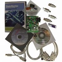
BOARD DEMO FOR MCF52221
Manufacturer
Freescale Semiconductor
Series
ColdFire®r
Type
MPUr
Datasheet
1.M52221DEMO.pdf
(56 pages)
Specifications of M52221DEMO
Contents
SBC, Cables and Software
Processor To Be Evaluated
MCF52221
Data Bus Width
32 bit
Interface Type
RS-232, USB
Silicon Manufacturer
Freescale
Core Architecture
Coldfire
Core Sub-architecture
Coldfire V2
Silicon Core Number
MCF52
Silicon Family Name
MCF5222x
Rohs Compliant
Yes
For Use With/related Products
MCF52221
Lead Free Status / RoHS Status
Lead free / RoHS Compliant


MCF52223 Family Configurations
1.2.2
The version 2 ColdFire processor core is comprised of two separate pipelines decoupled by an instruction buffer. The two-stage
instruction fetch pipeline (IFP) is responsible for instruction-address generation and instruction fetch. The instruction buffer is
a first-in-first-out (FIFO) buffer that holds prefetched instructions awaiting execution in the operand execution pipeline (OEP).
The OEP includes two pipeline stages. The first stage decodes instructions and selects operands (DSOC); the second stage
(AGEX) performs instruction execution and calculates operand effective addresses, if needed.
The V2 core implements the ColdFire instruction set architecture revision A+ with added support for a separate user stack
pointer register and four new instructions to assist in bit processing. Additionally, the MCF52223 core includes the
multiply-accumulate (MAC) unit for improved signal processing capabilities. The MAC implements a three-stage arithmetic
pipeline, optimized for 16×16 bit operations, with support for one 32-bit accumulator. Supported operands include 16- and
32-bit signed and unsigned integers, signed fractional operands, and a complete set of instructions to process these data types.
The MAC provides support for execution of DSP operations within the context of a single processor at a minimal hardware cost.
1.2.3
The ColdFire processor core debug interface is provided to support system debugging with low-cost debug and emulator
development tools. Through a standard debug interface, access to debug information and real-time tracing capability is provided
on 100-lead packages. This allows the processor and system to be debugged at full speed without the need for costly in-circuit
emulators.
The on-chip breakpoint resources include a total of nine programmable 32-bit registers: an address and an address mask register,
a data and a data mask register, four PC registers, and one PC mask register. These registers can be accessed through the
dedicated debug serial communication channel or from the processor’s supervisor mode programming model. The breakpoint
registers can be configured to generate triggers by combining the address, data, and PC conditions in a variety of single- or
dual-level definitions. The trigger event can be programmed to generate a processor halt or initiate a debug interrupt exception.
The MCF52223 implements revision B+ of the ColdFire Debug Architecture.
The MCF52223’s interrupt servicing options during emulator mode allow real-time critical interrupt service routines to be
serviced while processing a debug interrupt event. This ensures the system continues to operate even during debugging.
To support program trace, the V2 debug module provides processor status (PST[3:0]) and debug data (DDATA[3:0]) ports.
These buses and the PSTCLK output provide execution status, captured operand data, and branch target addresses defining
processor activity at the CPU’s clock rate. The MCF52223 includes a new debug signal, ALLPST. This signal is the logical
AND of the processor status (PST[3:0]) signals and is useful for detecting when the processor is in a halted state (PST[3:0] =
1111).
The full debug/trace interface is available only on the 100-pin packages. However, every product features the dedicated debug
serial communication channel (DSI, DSO, DSCLK) and the ALLPST signal.
1.2.4
The MCF52223 supports circuit board test strategies based on the Test Technology Committee of IEEE and the Joint Test Action
Group (JTAG). The test logic includes a test access port (TAP) consisting of a 16-state controller, an instruction register, and
three test registers (a 1-bit bypass register, a 112-bit boundary-scan register, and a 32-bit ID register). The boundary scan register
8
•
•
General purpose I/O interface
— Up to 56 bits of general purpose I/O
— Bit manipulation supported via set/clear functions
— Programmable drive strengths
— Unused peripheral pins may be used as extra GPIO
JTAG support for system level board testing
V2 Core Overview
Integrated Debug Module
JTAG
MCF52223 ColdFire Microcontroller, Rev. 2
Freescale Semiconductor
Related parts for M52221DEMO
Image
Part Number
Description
Manufacturer
Datasheet
Request
R

Part Number:
Description:
Manufacturer:
Freescale Semiconductor, Inc
Datasheet:
Part Number:
Description:
Manufacturer:
Freescale Semiconductor, Inc
Datasheet:
Part Number:
Description:
Manufacturer:
Freescale Semiconductor, Inc
Datasheet:
Part Number:
Description:
Manufacturer:
Freescale Semiconductor, Inc
Datasheet:
Part Number:
Description:
Manufacturer:
Freescale Semiconductor, Inc
Datasheet:
Part Number:
Description:
Manufacturer:
Freescale Semiconductor, Inc
Datasheet:
Part Number:
Description:
Manufacturer:
Freescale Semiconductor, Inc
Datasheet:
Part Number:
Description:
Manufacturer:
Freescale Semiconductor, Inc
Datasheet:
Part Number:
Description:
Manufacturer:
Freescale Semiconductor, Inc
Datasheet:
Part Number:
Description:
Manufacturer:
Freescale Semiconductor, Inc
Datasheet:
Part Number:
Description:
Manufacturer:
Freescale Semiconductor, Inc
Datasheet:
Part Number:
Description:
Manufacturer:
Freescale Semiconductor, Inc
Datasheet:
Part Number:
Description:
Manufacturer:
Freescale Semiconductor, Inc
Datasheet:
Part Number:
Description:
Manufacturer:
Freescale Semiconductor, Inc
Datasheet:
Part Number:
Description:
Manufacturer:
Freescale Semiconductor, Inc
Datasheet: