Z8F16800144ZCOG Zilog, Z8F16800144ZCOG Datasheet - Page 110
Z8F16800144ZCOG
Manufacturer Part Number
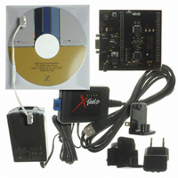
Z8F16800144ZCOG
Description
KIT DEV FOR Z8F642 MCU 44 PIN
Manufacturer
Zilog
Series
Z8 Encore!®r
Type
MCUr
Specifications of Z8F16800144ZCOG
Contents
Hardware, Software and Documentation
For Use With/related Products
Z8F642
For Use With
269-4661 - KIT ACC ETHERNET SMART CABLE
Lead Free Status / RoHS Status
Lead free / RoHS Compliant
Other names
269-4678


PS025011-1010
5. Write to the Timer Control 0 register to set the timer interrupt configuration field
6. Write to the Timer Reload High and Low Byte registers to set the Reload value (PWM
7. If desired, enable the timer interrupt and set the timer interrupt priority by writing to
8. Configure the associated GPIO port pin for the Timer Output and Timer Output
9. Write to the Timer Control 1 register to enable the timer and initiate counting.
The PWM period is given by the following equation:
If an initial starting value other than
registers, the ONE-SHOT mode equation must be used to determine the first PWM
timeout period.
If TPOL is set to 0, the ratio of the PWM output High time to the total period is given by:
If TPOL is set to 1, the ratio of the PWM output High time to the total period is given by:
CAPTURE Mode
In CAPTURE mode, the current timer count value is recorded when the desired external
Timer Input transition occurs. The Capture count value is written to the Timer PWM0
High and Low Byte Registers. The Timer counts timer clocks up to the 16-bit Reload
value. The TPOL bit in the Timer Control 1 register determines if the Capture occurs
on a rising edge or a falling edge of the Timer Input signal. When the Capture event
occurs, an interrupt is generated and the timer continues counting. The INPCAP bit in
Timer Control 0 register is set to indicate the timer interrupt is due to an input capture
event.
The timer continues counting up to the 16-bit Reload value stored in the Timer Reload
High and Low Byte registers. On reaching the Reload value, the timer generates an
interrupt and continues counting. The INPCAP bit in Timer Control 0 register is cleared to
indicate the timer interrupt is not due to an input capture event.
TICONFIG.
period). The Reload value must be greater than the PWM value.
the relevant interrupt registers.
Complement alternate functions.
PWM Output High Time Ratio (%)
PWM Output High Time Ratio (%)
PWM Period (s)
=
--------------------------------------------------------------------------- -
Timer Clock Frequency (Hz)
Reload Value
P R E L I M I N A R Y
=
=
0001H
Reload Value - PWM Value
------------------------------------------------------------------------ -
----------------------------------- -
Reload Value
PWM Value
Prescale
is loaded into the Timer High and Low Byte
Reload Value
100
Z8 Encore! XP
Product Specification
100
®
F1680 Series
Timers
96
Related parts for Z8F16800144ZCOG
Image
Part Number
Description
Manufacturer
Datasheet
Request
R

Part Number:
Description:
Communication Controllers, ZILOG INTELLIGENT PERIPHERAL CONTROLLER (ZIP)
Manufacturer:
Zilog, Inc.
Datasheet:

Part Number:
Description:
KIT DEV FOR Z8 ENCORE 16K TO 64K
Manufacturer:
Zilog
Datasheet:

Part Number:
Description:
KIT DEV Z8 ENCORE XP 28-PIN
Manufacturer:
Zilog
Datasheet:

Part Number:
Description:
DEV KIT FOR Z8 ENCORE 8K/4K
Manufacturer:
Zilog
Datasheet:

Part Number:
Description:
KIT DEV Z8 ENCORE XP 28-PIN
Manufacturer:
Zilog
Datasheet:

Part Number:
Description:
DEV KIT FOR Z8 ENCORE 4K TO 8K
Manufacturer:
Zilog
Datasheet:
Part Number:
Description:
CMOS Z8 microcontroller. ROM 16 Kbytes, RAM 256 bytes, speed 16 MHz, 32 lines I/O, 3.0V to 5.5V
Manufacturer:
Zilog, Inc.
Datasheet:
Part Number:
Description:
Low-cost microcontroller. 512 bytes ROM, 61 bytes RAM, 8 MHz
Manufacturer:
Zilog, Inc.
Datasheet:
Part Number:
Description:
Z8 4K OTP Microcontroller
Manufacturer:
Zilog, Inc.
Datasheet:
Part Number:
Description:
CMOS SUPER8 ROMLESS MCU
Manufacturer:
Zilog, Inc.
Datasheet:
Part Number:
Description:
SL1866 CMOSZ8 OTP Microcontroller
Manufacturer:
Zilog, Inc.
Datasheet:
Part Number:
Description:
SL1866 CMOSZ8 OTP Microcontroller
Manufacturer:
Zilog, Inc.
Datasheet:
Part Number:
Description:
OTP (KB) = 1, RAM = 125, Speed = 12, I/O = 14, 8-bit Timers = 2, Comm Interfaces Other Features = Por, LV Protect, Voltage = 4.5-5.5V
Manufacturer:
Zilog, Inc.
Datasheet:
Part Number:
Description:
Manufacturer:
Zilog, Inc.
Datasheet: