MPC566EVB Freescale Semiconductor, MPC566EVB Datasheet - Page 23
MPC566EVB
Manufacturer Part Number
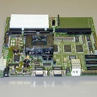
MPC566EVB
Description
KIT EVALUATION FOR MPC565/566
Manufacturer
Freescale Semiconductor
Specifications of MPC566EVB
Processor To Be Evaluated
MPC56x
Data Bus Width
32 bit
Interface Type
RS-232, Ethernet
Lead Free Status / RoHS Status
Contains lead / RoHS non-compliant


1.4.2 CAN PORTs and Options
The MPC566EVB board provides 3 CAN transceivers with I/O ports: CAN_A, CAN_B, and
CAN_C. CAN_A is supported by the PC33394 Power Oak CAN transceiver. The CAN_B and
CAN_C ports are supported by Philips PCA82C250 1M Baud CAN transceivers. The MPC566
CAN_A port is directly interfaced to the Power Oak transceiver and can not be isolated easily. The
MPC566 CAN_B and C ports are interfaced to the MPC566 TOUCAN channels B and C by option
jumpers B_RX, C_TX, and C_RX.
CAN_A
The CAN_A channel transceiver is provided by the Power Oak (PC33394). This transceiver has
software selectable options via the QSPI 0 channel which may communicate with the Power Oak
device. See the PC33394 data sheet for details. A 4.7K ohm pull-up is provided on the CAN_A
TX signal. Options S4 and S5 are provided near the Power Oak device to provide both MPC566
CAN_A and CAN_B channels for messaging on the Power Oak transceiver. If S4 and S5 are
connected, the B_RX option from the CAN_B port must be open.
B_RX Option Jumper
This option jumper enables the receive connection from the CAN_B port transceiver to the
MPC566 CAN B RX channel. The option allows the isolation of the CAN_B port transceiver RX
signal so that the user may use a different connection or transceiver for the MPC566 CAN B port.
C_RX and C_TX Option Jumpers
These options enable the CAN_C port transceiver RX and TX signals to be placed on the MPC566
MGPIO port CAN C signals. The CAN C operation on the MPC566 MGPIO port must be enabled
in software, see example source code. The MPC566 MGPIO Port bits 13 and 14 are effected along
with the MPC566EVB MIOS Port pins 32 and 33 respectfully.
B_EN and C_EN Option Pads, CN1 and CN2 Option Cut-Aways
These options provide access to the output enable and slew rate control of the respective CAN
transceiver. By default the transceivers are set to provide minimum slew rate (fast edge) and to be
constantly enabled for output. The configuration of the transceivers maybe modified for slew rate
or output control or both. Signaling CAN bus slew rate can be modified by increasing the value of
R66 and R67 for CAN_B and CAN_C respectfully. Opening the CN1 and CN2 away options for
CAN_B and CAN_C respectfully allows a MPC566 I/O port to be applied to the B_EN and C_EN
option pads to provide output control. A high level on the B_EN or C_EN would disable the
respective CAN transceiver output. See the PCA82C250 data sheet on the support CD for
additional information.
CAN_A, CAN_B, and CAN_C Port Connectors
These ports provide the CAN transceiver input and output connection to the CAN bus. The bias or
termination for the CAN bus is provided on the EVB board but not pupualted. If required the user
must install these components in the RAx, RBx, or RCx locations near the respective CAN port..
Following are the pin connections for the ports:
1
The MPC535/6 has limited or no functionality for this module. See Appendix A
Pin 1 = CAN-Hi level signal
Pin 2 = CAN-Lo level signal
Pin 3 = Ground or common (this is required for proper return path on CAN bus)
Freescale Semiconductor, Inc.
For More Information On This Product,
MPC566EVB User’s Manual
Go to: www.freescale.com
1
Communication Ports
1-13
Related parts for MPC566EVB
Image
Part Number
Description
Manufacturer
Datasheet
Request
R

Part Number:
Description:
Manufacturer:
Freescale Semiconductor, Inc
Datasheet:
Part Number:
Description:
Manufacturer:
Freescale Semiconductor, Inc
Datasheet:
Part Number:
Description:
Manufacturer:
Freescale Semiconductor, Inc
Datasheet:
Part Number:
Description:
Manufacturer:
Freescale Semiconductor, Inc
Datasheet:
Part Number:
Description:
Manufacturer:
Freescale Semiconductor, Inc
Datasheet:
Part Number:
Description:
Manufacturer:
Freescale Semiconductor, Inc
Datasheet:
Part Number:
Description:
Manufacturer:
Freescale Semiconductor, Inc
Datasheet:
Part Number:
Description:
Manufacturer:
Freescale Semiconductor, Inc
Datasheet:
Part Number:
Description:
Manufacturer:
Freescale Semiconductor, Inc
Datasheet:
Part Number:
Description:
Manufacturer:
Freescale Semiconductor, Inc
Datasheet:
Part Number:
Description:
Manufacturer:
Freescale Semiconductor, Inc
Datasheet:
Part Number:
Description:
Manufacturer:
Freescale Semiconductor, Inc
Datasheet:
Part Number:
Description:
Manufacturer:
Freescale Semiconductor, Inc
Datasheet:
Part Number:
Description:
Manufacturer:
Freescale Semiconductor, Inc
Datasheet:
Part Number:
Description:
Manufacturer:
Freescale Semiconductor, Inc
Datasheet: