MPC566EVB Freescale Semiconductor, MPC566EVB Datasheet - Page 43
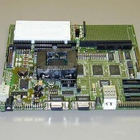
MPC566EVB
Manufacturer Part Number
MPC566EVB
Description
KIT EVALUATION FOR MPC565/566
Manufacturer
Freescale Semiconductor
Specifications of MPC566EVB
Processor To Be Evaluated
MPC56x
Data Bus Width
32 bit
Interface Type
RS-232, Ethernet
Lead Free Status / RoHS Status
Contains lead / RoHS non-compliant


2.2 Installation And Setup
The following sections describe all the steps needed to prepare the board for operation. Please read
the following sections carefully before using the board. When you are preparing the board for the
first time, be sure to check that all jumpers and switches are in the default locations. Default
jumper and switch settings are documented on the master jumper table (see Table 1-2). After the
board is functional in its default mode, the Ethernet interface may be used by following the
instructions provided in Appendix B, “Configuring dBUG for Network Downloads.
2.2.1 Unpacking
Unpack the computer board from its shipping box. Save the box for storing or reshipping. Refer
to the following list and verify that all the items are present. You should have received:
Once you have verified that all the items are present, remove the board from its protective jacket
and anti-static bag. Check the board for any visible damage. Ensure that there are no broken,
damaged, or missing parts. If you have not received all the items listed above or they are damaged,
please contact Axiom manufacturing immediately - for contact details please see the front of this
manual.
2.2.2 Preparing the Board for Use
The board, as shipped, is ready to be connected to a terminal and power supply without any need
for modification. Figure 2-3, “Jumper Locations”, shows the position of the jumpers and
connectors.
2.2.3 Providing Power to the Board
The board accepts two means of power supply connection, either PWR or TB1. Connector PWR
is a 2.1mm power jack and TB1 is a power clamp connector with inputs of +12VDC, Ground, and
an IGN (ignition) signal. If not using the provided power supply, the board accepts a supply volt-
age of 4 - 26VDC (current 300ma typical at 12VDC input).
•
•
•
•
•
•
•
•
MPC566EVB Single Board Computer
MPC566EVB User's Manual (this document)
One RS232 9-pin Serial Cable
One CAT5E Ethernet cable, crossover type
One P&E Micro BDM (Background Debug Mode) “wiggler” cable
MPC5xx support CD with all documents, drawings, source codes, examples, AxIDE
software, and GNU compiler.
25-pin parallel cable (DB32 M/F) for BDM
A selection of demo Third Party Developer Tools and Literature
Avoid touching the MOS devices. Static discharge can and will
damage these devices.
Freescale Semiconductor, Inc.
For More Information On This Product,
Chapter 2. Initialization and Setup
Go to: www.freescale.com
NOTE:
Installation And Setup
2-3
Related parts for MPC566EVB
Image
Part Number
Description
Manufacturer
Datasheet
Request
R

Part Number:
Description:
Manufacturer:
Freescale Semiconductor, Inc
Datasheet:
Part Number:
Description:
Manufacturer:
Freescale Semiconductor, Inc
Datasheet:
Part Number:
Description:
Manufacturer:
Freescale Semiconductor, Inc
Datasheet:
Part Number:
Description:
Manufacturer:
Freescale Semiconductor, Inc
Datasheet:
Part Number:
Description:
Manufacturer:
Freescale Semiconductor, Inc
Datasheet:
Part Number:
Description:
Manufacturer:
Freescale Semiconductor, Inc
Datasheet:
Part Number:
Description:
Manufacturer:
Freescale Semiconductor, Inc
Datasheet:
Part Number:
Description:
Manufacturer:
Freescale Semiconductor, Inc
Datasheet:
Part Number:
Description:
Manufacturer:
Freescale Semiconductor, Inc
Datasheet:
Part Number:
Description:
Manufacturer:
Freescale Semiconductor, Inc
Datasheet:
Part Number:
Description:
Manufacturer:
Freescale Semiconductor, Inc
Datasheet:
Part Number:
Description:
Manufacturer:
Freescale Semiconductor, Inc
Datasheet:
Part Number:
Description:
Manufacturer:
Freescale Semiconductor, Inc
Datasheet:
Part Number:
Description:
Manufacturer:
Freescale Semiconductor, Inc
Datasheet:
Part Number:
Description:
Manufacturer:
Freescale Semiconductor, Inc
Datasheet: