MPC566EVB Freescale Semiconductor, MPC566EVB Datasheet - Page 57
MPC566EVB
Manufacturer Part Number
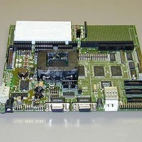
MPC566EVB
Description
KIT EVALUATION FOR MPC565/566
Manufacturer
Freescale Semiconductor
Specifications of MPC566EVB
Processor To Be Evaluated
MPC56x
Data Bus Width
32 bit
Interface Type
RS-232, Ethernet
Lead Free Status / RoHS Status
Contains lead / RoHS non-compliant


Freescale Semiconductor, Inc.
Operational Procedure
exception vector, the user places the address of the exception handler in the appropriate vector in
the vector table located at 0xFFF0_0000.
The Software Watchdog Timer is disabled and internal timers are placed in a stop condition.
Interrupt controller registers are initialized with unique interrupt level/priority pairs. Please refer
to the dBUG source files on the PowerPC website (www.motorola.com/powerpc) for the complete
initialization code sequence.
After initialization, the terminal will display:
Part Number: 0x36
MaskNum: 0x10
Copyright 1995-2002 Motorola, Inc.
All Rights Reserved.
MPC566 MPC566EVB Firmware v2e.1a.xx (Build XXX on XXX
XX 20XX xx:xx:xx)
Enter 'help' for help.
dBUG>
If you did not get this response check the setup, refer to Section 2.4, “System Power-up and Initial
Operation”.
Other means can be used to re-initialize the MPC566EVB Computer Board firmware. These
means are discussed in the following paragraphs.
3.2.2.1 Hard RESET Button.
Pressing the Hard RESET button (SW1-HARD RESET) causes all processes to terminate, resets
the MPC566 processor and board logic and restarts the dBUG firmware. Pressing the RESET
button would be the appropriate action if all else fails.
3.2.2.2 Non-Maskable Interrupt Button.
SWITCH1 can be used as a non-maskable interrupt button. It is available for the user to use in their
code as an input if the jumper BRK_EN is removed. The NMI function causes an interrupt of the
present processing (a level 0 interrupt on MPC566) and gives control to the dBUG firmware. This
action differs from RESET in that no processor register or memory contents are changed, the
processor and peripherals are not reset, and dBUG is not restarted. Also, in response to depressing
the NMI button, the contents of the MPC566 core internal registers are displayed.
The NMI function is most appropriate when software is being debugged. The user can interrupt
the processor without destroying the present state of the system. This is accomplished by forcing
a non-maskable interrupt that will call a dBUG routine that will save the current state of the
registers to shadow registers in the monitor for display to the user. The user will be returned to the
ROM monitor prompt after exception handling.
3.2.2.3 Software Reset Command.
dBUG does have a command that causes dBUG to restart as if a hardware reset was invoked. The
command is "RESET".
Chapter 3. Using the Monitor/Debug Firmware
3-5
For More Information On This Product,
Go to: www.freescale.com
Related parts for MPC566EVB
Image
Part Number
Description
Manufacturer
Datasheet
Request
R

Part Number:
Description:
Manufacturer:
Freescale Semiconductor, Inc
Datasheet:
Part Number:
Description:
Manufacturer:
Freescale Semiconductor, Inc
Datasheet:
Part Number:
Description:
Manufacturer:
Freescale Semiconductor, Inc
Datasheet:
Part Number:
Description:
Manufacturer:
Freescale Semiconductor, Inc
Datasheet:
Part Number:
Description:
Manufacturer:
Freescale Semiconductor, Inc
Datasheet:
Part Number:
Description:
Manufacturer:
Freescale Semiconductor, Inc
Datasheet:
Part Number:
Description:
Manufacturer:
Freescale Semiconductor, Inc
Datasheet:
Part Number:
Description:
Manufacturer:
Freescale Semiconductor, Inc
Datasheet:
Part Number:
Description:
Manufacturer:
Freescale Semiconductor, Inc
Datasheet:
Part Number:
Description:
Manufacturer:
Freescale Semiconductor, Inc
Datasheet:
Part Number:
Description:
Manufacturer:
Freescale Semiconductor, Inc
Datasheet:
Part Number:
Description:
Manufacturer:
Freescale Semiconductor, Inc
Datasheet:
Part Number:
Description:
Manufacturer:
Freescale Semiconductor, Inc
Datasheet:
Part Number:
Description:
Manufacturer:
Freescale Semiconductor, Inc
Datasheet:
Part Number:
Description:
Manufacturer:
Freescale Semiconductor, Inc
Datasheet: