PESD1LIN,115 NXP Semiconductors, PESD1LIN,115 Datasheet - Page 6
PESD1LIN,115
Manufacturer Part Number
PESD1LIN,115
Description
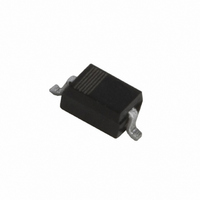
DIODE ESD PROTECTION SOD323
Manufacturer
NXP Semiconductors
Datasheet
1.PESD1LIN115.pdf
(11 pages)
Specifications of PESD1LIN,115
Package / Case
SC-76, SOD-323, UMD2
Voltage - Reverse Standoff (typ)
15V
Voltage - Breakdown
17.1V
Power (watts)
160W
Polarization
Bidirectional
Mounting Type
Surface Mount
Polarity
Bidirectional
Clamping Voltage
25 V
Operating Voltage
24 V
Breakdown Voltage
18.9 V
Termination Style
SMD/SMT
Peak Surge Current
3 A
Peak Pulse Power Dissipation
160 W
Capacitance
17 pF
Maximum Operating Temperature
+ 150 C
Minimum Operating Temperature
- 65 C
Dimensions
1.35 mm W x 2.7 mm L x 1.1 mm H
Number Of Elements
1
Operating Temperature Classification
Military
Reverse Breakdown Voltage
25.4V
Reverse Stand-off Voltage
24V
Leakage Current (max)
50nA
Peak Pulse Current
3A
Test Current (it)
5mA
Operating Temp Range
-65C to 150C
Mounting
Surface Mount
Pin Count
2
Lead Free Status / RoHS Status
Lead free / RoHS Compliant
Lead Free Status / RoHS Status
Lead free / RoHS Compliant, Lead free / RoHS Compliant
Other names
568-4033-2
934058897115
PESD1LIN T/R
PESD1LIN T/R
934058897115
PESD1LIN T/R
PESD1LIN T/R
Available stocks
Company
Part Number
Manufacturer
Quantity
Price

Part Number:
PESD1LIN,115
Manufacturer:
NEXPERIA/安世
Quantity:
20 000


NXP Semiconductors
7. Application information
PESD1LIN_2
Product data sheet
The PESD1LIN is designed for the protection of one LIN bus signal line from the damage
caused by ESD and surge pulses. The PESD1LIN provides a surge capability of up to
160 W per line for a 8/20 s waveform.
Circuit board layout and protection device placement
Circuit board layout is critical for the suppression of ESD, Electrical Fast Transient (EFT)
and surge transients. The following guidelines are recommended:
1. Place the PESD1LIN as close to the input terminal or connector as possible.
2. The path length between the PESD1LIN and the protected line should be minimized.
3. Keep parallel signal paths to a minimum.
4. Avoid running protection conductors in parallel with unprotected conductor.
5. Minimize all Printed-Circuit Board (PCB) conductive loops including power and
6. Minimize the length of the transient return path to ground.
7. Avoid using shared transient return paths to a common ground point.
8. Ground planes should be used whenever possible. For multilayer PCBs, use ground
Fig 6.
ground loops.
vias.
Typical application: ESD protection of one automotive LIN bus line
power application (e.g. electro motor, inductive loads)
application (e.g. voltage regulator and microcontroller)
Rev. 02 — 12 November 2008
transceiver
GND
BAT
LIN
LIN
C MASTER/SLAVE
C BAT
PESD1LIN
24 V
15 V
LIN bus ESD protection diode
connector
LIN node
006aaa678
PESD1LIN
© NXP B.V. 2008. All rights reserved.
6 of 11
Related parts for PESD1LIN,115
Image
Part Number
Description
Manufacturer
Datasheet
Request
R

Part Number:
Description:
PESD1LIN in a very small SOD323 (SC-76) Surface-Mounted Device (SMD) plasticpackage designed to protect one automotive Local Interconnect Network (LIN) bus linefrom the damage caused by ElectroStatic Discharge (ESD) and other transients
Manufacturer:
NXP Semiconductors
Datasheet:

Part Number:
Description:
TVS Diodes - Transient Voltage Suppressors LIN-BUS ESD PROTECT
Manufacturer:
NXP Semiconductors
Datasheet:
Part Number:
Description:
NXP Semiconductors designed the LPC2420/2460 microcontroller around a 16-bit/32-bitARM7TDMI-S CPU core with real-time debug interfaces that include both JTAG andembedded trace
Manufacturer:
NXP Semiconductors
Datasheet:

Part Number:
Description:
NXP Semiconductors designed the LPC2458 microcontroller around a 16-bit/32-bitARM7TDMI-S CPU core with real-time debug interfaces that include both JTAG andembedded trace
Manufacturer:
NXP Semiconductors
Datasheet:
Part Number:
Description:
NXP Semiconductors designed the LPC2468 microcontroller around a 16-bit/32-bitARM7TDMI-S CPU core with real-time debug interfaces that include both JTAG andembedded trace
Manufacturer:
NXP Semiconductors
Datasheet:
Part Number:
Description:
NXP Semiconductors designed the LPC2470 microcontroller, powered by theARM7TDMI-S core, to be a highly integrated microcontroller for a wide range ofapplications that require advanced communications and high quality graphic displays
Manufacturer:
NXP Semiconductors
Datasheet:
Part Number:
Description:
NXP Semiconductors designed the LPC2478 microcontroller, powered by theARM7TDMI-S core, to be a highly integrated microcontroller for a wide range ofapplications that require advanced communications and high quality graphic displays
Manufacturer:
NXP Semiconductors
Datasheet:
Part Number:
Description:
The Philips Semiconductors XA (eXtended Architecture) family of 16-bit single-chip microcontrollers is powerful enough to easily handle the requirements of high performance embedded applications, yet inexpensive enough to compete in the market for hi
Manufacturer:
NXP Semiconductors
Datasheet:
Part Number:
Description:
The XA-S3 device is a member of Philips Semiconductors? XA(eXtended Architecture) family of high performance 16-bitsingle-chip microcontrollers
Manufacturer:
NXP Semiconductors
Datasheet:

Part Number:
Description:
The NXP BlueStreak LH75401/LH75411 family consists of two low-cost 16/32-bit System-on-Chip (SoC) devices
Manufacturer:
NXP Semiconductors
Datasheet:
Part Number:
Description:
The NXP LPC3130/3131 combine an 180 MHz ARM926EJ-S CPU core, high-speed USB2
Manufacturer:
NXP Semiconductors
Datasheet:
Part Number:
Description:
The NXP LPC3141 combine a 270 MHz ARM926EJ-S CPU core, High-speed USB 2
Manufacturer:
NXP Semiconductors
Part Number:
Description:
The NXP LPC3143 combine a 270 MHz ARM926EJ-S CPU core, High-speed USB 2
Manufacturer:
NXP Semiconductors

Part Number:
Description:
The NXP LPC3152 combines an 180 MHz ARM926EJ-S CPU core, High-speed USB 2
Manufacturer:
NXP Semiconductors