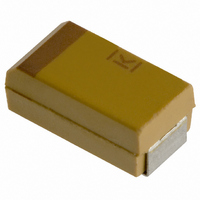
T491B155K025AS Kemet, T491B155K025AS Datasheet - Page 11

T491B155K025AS
Manufacturer Part Number
T491B155K025AS
Description
CAPACITOR TANT 1.5UF 25V 10% SMD
Manufacturer
Kemet
Series
T491r
Type
Moldedr
Datasheet
1.T491B155K025AS.pdf
(100 pages)
Specifications of T491B155K025AS
Capacitance
1.5µF
Voltage - Rated
25V
Tolerance
±10%
Esr (equivalent Series Resistance)
5.000 Ohm
Operating Temperature
-55°C ~ 125°C
Mounting Type
Surface Mount
Package / Case
1210 (3528 Metric)
Size / Dimension
0.138" L x 0.110" W (3.50mm x 2.80mm)
Height
0.075" (1.90mm)
Manufacturer Size Code
B
Features
General Purpose
Lead Free Status / RoHS Status
Contains lead / RoHS non-compliant
Lead Spacing
-
Other names
399-1625-2
T510E, T530E
Power dissipation is a function of capacitor size
and materials. Maximum power ratings have been
established for all case sizes to prevent overheat-
ing. In actual use, the capacitor’s ability to dissi-
pate the heat generated at any given power level
may be affected by a variety of circuit factors.
These include board density, pad size, heat sinks
and air circulation.
T510X, T530X
ESR and Z are also affected by temperature. At
100 kHz, ESR decreases with increasing temper-
ature. The amount of change is influenced by the
size of the capacitor and is generally more pro-
nounced on smaller ratings.
KEMET
T530D
R
S
U
V
A
B
C
D
E
T
X
Case Code
©KEMET Electronics Corporation, P.O. Box 5928, Greenville, S.C. 29606, (864) 963-6300
2012-12
3216-12
3528-12
6032-15
7343-20
3216-18
3528-21
3062-28
7343-31
7343-43
7260-38
7343-31
7343-43
7260-38
EIA
SOLID TANTALUM CHIP CAPACITORS
Maximum Power Dissipation
mW @ +25°C w/+20°C Rise
125
110
150
165
200
255
270
285
25
60
70
90
75
85
*+12% is standard. +15% or +20% applies to certain CV values
Contact KEMET representative for details.
**within 1.5x initial limit for extended CV values.
***within 1.15x initial limit for extended CV values.
Step
No.
1
2
3
4
5
6
Permissible AC ripple voltage and current are
related to equivalent series resistance (ESR) and
power dissipation capability.
Permissible AC ripple voltage which may be
applied is limited by three criteria:
a. The positive peak AC voltage plus the DC
b. The negative peak AC voltage, in combination
c. The power dissipated in the ESR of the capa-
Actual power dissipated may be calculated from
the following:
P = l
Substituting I = E
where:
I = rms ripple current (amperes)
E = rms ripple voltage (volts)
P = power (watts)
Z = impedance at specified frequency (ohms)
R = equivalent series resistance at specified
Using P max from Table 5, maximum allowable
rms ripple current or voltage may be determined
as follows:
I (max) =
These values should be derated at elevated tem-
peratures as follows:
bias voltage, if any, must not exceed the DC
voltage rating of the capacitor.
with the bias voltage, if any, must not exceed
the permissible reverse voltage ratings pre-
sented in Table 3.
citor must not exceed the appropriate value
specified in Table 5.
Temperature
+125 C *within ± 12%or within 12X
+ 85 C within ± 10%
+25 C
+25 C
+25 C
-55 C
Temp.
frequency (ohms)
2
125 C
R
85 C
within specified within original within original
tolerance
within ± 10%
of initial value
within ± 5%
of initial value
of initial value
20% of initial
value
within ± 5%
of initial value
Capacitance
P max /
Z
,
R
P = E
Derating Factor
E (max) = Z
limit
N/A
within original within original
limit
within 10X
original limit
original limit
within original within original
limit
Leakage
Current
Z
2
R
.9
.4
2
limit
within original
limit**
limit**
within original
limit***
within original
limit***
limit
Dissipation
P max /
Factor
R
9


