T491B155K025AS Kemet, T491B155K025AS Datasheet - Page 50
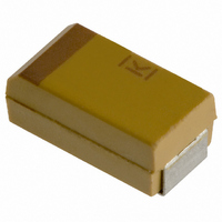
T491B155K025AS
Manufacturer Part Number
T491B155K025AS
Description
CAPACITOR TANT 1.5UF 25V 10% SMD
Manufacturer
Kemet
Series
T491r
Type
Moldedr
Datasheet
1.T491B155K025AS.pdf
(100 pages)
Specifications of T491B155K025AS
Capacitance
1.5µF
Voltage - Rated
25V
Tolerance
±10%
Esr (equivalent Series Resistance)
5.000 Ohm
Operating Temperature
-55°C ~ 125°C
Mounting Type
Surface Mount
Package / Case
1210 (3528 Metric)
Size / Dimension
0.138" L x 0.110" W (3.50mm x 2.80mm)
Height
0.075" (1.90mm)
Manufacturer Size Code
B
Features
General Purpose
Lead Free Status / RoHS Status
Contains lead / RoHS non-compliant
Lead Spacing
-
Other names
399-1625-2


48
29. Handling
30. Termination Coating
31. Recommended Mounting Pad Geometries
Table 6 - Land Pattern Dimensions for Reflow Solder
KEMET/EIA Size Code
W/7343-15, X/7343-43,
Y/7343-40
KEMET’s standard termination finish is 100% Sn.
Standard terminations can be ordered with a “T”
suffix in the lead material designator of the KEMET
part number. Components ordered with the “T” suf-
fix are Pb-Free/RoHS compliant and are backward
and forward compatible with SnPb and Pb-Free sol-
dering processes.
90Sn/10Pb terminations are also available and can
be ordered with an “H” suffix.
KEMET’s “S” suffix remains an active termination
designator for current designs but is not recom-
mended for new designs. Parts ordered with an “S”
suffix are not guaranteed to be Pb-Free or RoHS
compliant. Refer to www.kemet.com for information
on Pb-Free transition.
Proper mounting pad geometries are essential for
successful solder connections. These dimensions
are highly process sensitive and should be designed
B/3528-21, T/3528-12
C/6032-28
D/7343-31, V/7343-20,
Automatic handling of encapsulated components is
enhanced by the molded case which provides com-
patibility with all types of high speed pick and place
equipment. Manual handling of these devices pre-
sents no unique problems. Care should be taken
with your fingers, however, to avoid touching the
solder-coated terminations as body oils, acids and
salts will degrade the solderability of these termina-
tions. Finger cots should be used whenever manu-
ally handling all solderable surfaces.
X
©KEMET Electronics Corporation, P.O. Box 5928, Greenville, S.C. 29606, (864) 963-6300
CONDUCTIVE POLYMER CHIP CAPACITORS
Z
C
G
Y
Grid
Placement
Courtyard
5.00 1.10 2.50 1.95 3.05
7.60 2.50 2.50 2.55 5.05
8.90 3.80 2.70 2.55
Z
G
Pad Dimensions
X
(ref) (ref)
Y
6.35
C
32. Soldering
to maximize the intergrity of the solder joint, and to
minimize component rework due to unacceptable
solder joints.
Figure 5 illustrates pad geometry. The table pro-
vides recommended pad dimensions for reflow sol-
dering techniques. These dimensions are intended
to be a starting point for circuit board designers, to
be fine tuned, if necessary, based upon the pecu-
liarities of the soldering process and/or circuit board
design.
Visit KEMET.com for Engineering Bulletin Number
F-2100 entitled “Surface Mount Mounting Pad
Dimensions and Considerations” for further details
on this subject.
The T52X KO-CAP family has been designed for
reflow solder processes. Solder-coated terminations
have excellent wetting characteristics for high integrity
solder fillets. Preheating of these components is rec-
ommended to avoid extreme thermal stress. Pb (lead)
Free peak temperature is 260˚C (with up to 3x reflow
capabilities).
Hand-soldering should be avoided. If necessary, it
should be performed with care due to the difficulty
in process control. Care should be taken to avoid
contact of the soldering iron to the molded case.
300
250
200
150
100
50
0
0
60 Sec.
50
90 Sec.
100
Time (Seconds)
150
5 Sec.
45 Sec.
95 Sec.
200
45 Sec.
250
300
Related parts for T491B155K025AS
Image
Part Number
Description
Manufacturer
Datasheet
Request
R

Part Number:
Description:
CAP, KEMET #F601BL105K250C
Manufacturer:
Kemet
Datasheet:
Part Number:
Description:
Manufacturer:
Kemet
Datasheet:
Part Number:
Description:
Manufacturer:
Kemet
Datasheet: