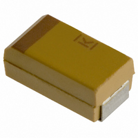
T491B155K025AS Kemet, T491B155K025AS Datasheet - Page 49

T491B155K025AS
Manufacturer Part Number
T491B155K025AS
Description
CAPACITOR TANT 1.5UF 25V 10% SMD
Manufacturer
Kemet
Series
T491r
Type
Moldedr
Datasheet
1.T491B155K025AS.pdf
(100 pages)
Specifications of T491B155K025AS
Capacitance
1.5µF
Voltage - Rated
25V
Tolerance
±10%
Esr (equivalent Series Resistance)
5.000 Ohm
Operating Temperature
-55°C ~ 125°C
Mounting Type
Surface Mount
Package / Case
1210 (3528 Metric)
Size / Dimension
0.138" L x 0.110" W (3.50mm x 2.80mm)
Height
0.075" (1.90mm)
Manufacturer Size Code
B
Features
General Purpose
Lead Free Status / RoHS Status
Contains lead / RoHS non-compliant
Lead Spacing
-
Other names
399-1625-2
21. Resistance to Solvents
22. Fungus
23. Flammability
24. Resistance to Soldering Heat
25. Solderability
Failure rates may be improved in application by
derating the voltage applied to the capacitor.
KEMET recommends that KO-CAPs be derated
to 90% or less of the rated voltage in application
for part types
ed to 80% or less of the rated voltage.
KO-CAPs exhibit a benign failure mode in that
they do not fail catastophically even under typical
fault conditions. If a shorted capacitor is allowed
to pass unlimited current, it may overheat and the
case may discolor. But this is distinctly different
from the “ignition” that may occur with standard
MnO2 cathode tantalums. Replacement of the
MnO2 by the polymer removes the oxygen that
fuels ignition during a failure event.
• Mil-Std-202, Method 215
Post Test Performance:
oxidize into a more resistive material that elimi-
nates the defect site in the dielectric and reduces
the flow of current.
Capacitor failure may be induced by exceeding
the rated conditions of forward DC voltage,
reverse DC voltage, surge current, power dissipa-
tion or temperature. Excessive environmental
stress, such as prolonged or high temperature
reflow processes may also trigger dielectric failure
• Mil-Std-810, Method 508
• UL94 VO Classification
• Maximum Reflow
• Typical Reflow
Post Test Performance:
• Mil-Std-202, Method 208
• ANSI/J-STD-002, Test B
a. Capacitance — within ±10% of initial value
b. DC Leakage — within initial limit
c. Dissipation Factor — within initial limit
d. ESR — within initial limit
e. Physical — no degradation of case, terminals
or marking
a. Capacitance — within ±10% of initial value
b. DC Leakage — within initial limit
c. Dissipation Factor — within initial limit
d. ESR — within initial limit
Applies to Solder Coated terminations only.
Encapsulant materials meet this classifaction
+240 ±5ºC, 10 seconds
+230 ±5ºC, 30 seconds
©KEMET Electronics Corporation, P.O. Box 5928, Greenville, S.C. 29606, (864) 963-6300
MECHANICAL
CONDUCTIVE POLYMER CHIP CAPACITORS
10V. Parts > 10V should be derat-
.
26. Vibration
27. Shock
28. Terminal Strength
Post Test Performance:
within initial limit
KEMET
a. Capacitance — within ±5% of initial value
b. DC Leakage — within initial limit
c. Dissipation Factor —
d. ESR - within initial limit
• Pull Force
• Mil-Std-202, Method 204, Condition D, 10 Hz
to 2,000 Hz, 20G Peak
Post Test Performance:
100 G Peak
Post Test Performance:
• Tensile Force
W
B
C
D
A
T
V
Y
X
a. Capacitance — within ±10% of initial value
b. DC Leakage — within initial limit
c. Dissipation Factor — within initial limit
d. ESR — within initial limit
a. Capacitance — within ±10% of initial value
b. DC Leakage — within initial limit
c. Dissipation Factor — within initial limit
d. ESR - within initial limit
Mil-Std-202, Method 213, Condition I,
Case Code
One Pound (454 grams), 30 Seconds
Four Pounds (1.8 kilograms), 60 Seconds
3216-18
3528-12
3528-21
6032-28
7343-20
7343-15
7343-31
7343-40
7343-43
EIA
4 lb. (1.8 Kg)
Kilograms
Maximum Shear Loads
3.2
3.6
3.6
4.5
5.0
5.0
5.0
5.0
5.0
4
Pounds
10.0
11.0
11.0
11.0
11.0
11.0
7.0
8.0
8.0
47


