T491B155K025AS Kemet, T491B155K025AS Datasheet - Page 8
T491B155K025AS
Manufacturer Part Number
T491B155K025AS
Description
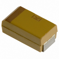
CAPACITOR TANT 1.5UF 25V 10% SMD
Manufacturer
Kemet
Series
T491r
Type
Moldedr
Datasheet
1.T491B155K025AS.pdf
(100 pages)
Specifications of T491B155K025AS
Capacitance
1.5µF
Voltage - Rated
25V
Tolerance
±10%
Esr (equivalent Series Resistance)
5.000 Ohm
Operating Temperature
-55°C ~ 125°C
Mounting Type
Surface Mount
Package / Case
1210 (3528 Metric)
Size / Dimension
0.138" L x 0.110" W (3.50mm x 2.80mm)
Height
0.075" (1.90mm)
Manufacturer Size Code
B
Features
General Purpose
Lead Free Status / RoHS Status
Contains lead / RoHS non-compliant
Lead Spacing
-
Other names
399-1625-2


*+12% is standard. +15% and 20% apply to certain
extended CV values as noted in part number tables.
6
@ +25°C
Working
& +85°C
Refer to part number tables for available voltage
ratings by series.
These voltages are the maximum recommended peak
DC operating voltages from –55°C to +85°C for
continuous duty. These voltages are derated linearly above
+85°C to 2/3 rated voltage for operation at
+125°C (See Figure 3). For added reliability it is
recommended to operate at a 50% derating of the working
voltage for tantalum capacitors with MnO
See page 39 for working DC Voltage of high temperature
T498 product.
Rated
Volts
3 to 50 volts
10
16
20
25
35
50
100%
–55°C
–10%
80%
60%
40%
20%
3
4
6
-60
@ +25°C
& +85°C
Voltage
-40
Surge
©KEMET Electronics Corporation, P.O. Box 5928, Greenville, S.C. 29606, (864) 963-6300
Ambient Temperature
13
20
26
33
46
65
4
5.2
8
-20
+85°C
+10%
SOLID TANTALUM CHIP CAPACITORS
0
Operating Temperature— C
+20 +40 +60 +80 +100 +120 +140
@ +125°C
Derated
Volts
DC
10
13
17
23
33
2
2.7
4
7
*+12% or +15%to20%
°
+125°C
2
@ +125°C
as a cathode.
Voltage
Surge
12
16
20
28
40
2.4
3.2
5
8
+25°C
+85°C
+125°C
Surge voltage tests are performed at +25°C,
+85°C and +125°C with the applicable surge volt-
age. The surge voltage is applied for 1000 cycles
of 30 seconds at voltage through a 33 ohm series
resistor and 30 seconds off voltage with the
capacitor discharged through a 33 ohm resistor.
Upon completing the test, the capacitors are
allowed to stabilize at room temperature. Capaci-
tance, DCL and DF are then tested:
a.
b.
c.
d.
Solid tantalum capacitors are polarized devices
and may be permanently damaged or destroyed if
connected with the wrong polarity. The positive
terminal is identified on the capacitor body by a
stripe and a beveled edge. A small degree of tran-
sient reverse voltage is permissible for short peri-
ods per Table 3. The capacitors should not be
operated continuously in reverse mode, even with-
in these limits.
Refer to part number tables for maximum leakage
current limits.
DC leakage current is the current that, after a one-
to five-minute charging period, flows through a
capacitor when voltage is applied. Leakage is
measured at +25°C with full rated DC voltage
applied to the capacitor through a 1000 ohm resis-
tor in series with the capacitor.
DC leakage current increases with increasing tem-
perature.
–55°C
N/A
Capacitance — within ± 5% of initial value
DC Leakage — within initial limit
Dissipation Factor — within initial limit
ESR — within initial limit
Ambient Temperature
+85°C
10X
°
+125°C
12X
Related parts for T491B155K025AS
Image
Part Number
Description
Manufacturer
Datasheet
Request
R

Part Number:
Description:
CAP, KEMET #F601BL105K250C
Manufacturer:
Kemet
Datasheet:
Part Number:
Description:
Manufacturer:
Kemet
Datasheet:
Part Number:
Description:
Manufacturer:
Kemet
Datasheet: