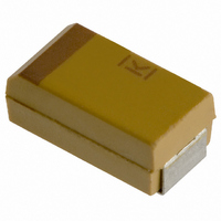
T491B155K025AS Kemet, T491B155K025AS Datasheet - Page 48

T491B155K025AS
Manufacturer Part Number
T491B155K025AS
Description
CAPACITOR TANT 1.5UF 25V 10% SMD
Manufacturer
Kemet
Series
T491r
Type
Moldedr
Datasheet
1.T491B155K025AS.pdf
(100 pages)
Specifications of T491B155K025AS
Capacitance
1.5µF
Voltage - Rated
25V
Tolerance
±10%
Esr (equivalent Series Resistance)
5.000 Ohm
Operating Temperature
-55°C ~ 125°C
Mounting Type
Surface Mount
Package / Case
1210 (3528 Metric)
Size / Dimension
0.138" L x 0.110" W (3.50mm x 2.80mm)
Height
0.075" (1.90mm)
Manufacturer Size Code
B
Features
General Purpose
Lead Free Status / RoHS Status
Contains lead / RoHS non-compliant
Lead Spacing
-
Other names
399-1625-2
46
12. Temperature Stability
13. Standard Life Test
Step Temp.
1
2
3
4
5
6
• 85ºC, Rated Voltage, 2000 Hours
Post Test Performance:
Mounted capacitors withstand extreme tempera-
ture testing at a succession of continuous steps
at +25ºC, -55ºC, +25ºC, +85ºC, +105ºC, +25ºC in
that order*. Capacitors are allowed to stabilize at
each temperature before measurement. Cap, DF,
and DCL are measured at each temperature
except DC Leakage is not measured at -55ºC.
*Maximum temperature 125ºC for T525 and T530 series.
Acceptable limits are as follows:
Actual power dissipated may be calculated from
the following:
P =I
Substituting I = E,
where:
I = rms ripple current (amperes)
E = rms ripple voltage (volts)
P = power (watts)
Z = impedance at specified frequency (ohms)
R = equivalent series resistance at specified
Using P max from Table 3, maximum allowable
rms ripple current or voltage may be determined as
follows:
I(max) =
These values should be derated at elevated tem-
peratures as follows:
a. Capacitance: within -20%/+10% of initial value
b. DF: within initial limit
c. DC Leakage: within initial limit
d. ESR: within initial limit
T525, T530)
+105ºC
(125ºC for
Temperature
+25ºC
+25ºC
+85ºC
+25ºC
-55ºC
2
©KEMET Electronics Corporation, P.O. Box 5928, Greenville, S.C. 29606, (864) 963-6300
frequency (ohms)
R
125ºC
85ºC
ENVIRONMENTAL
CONDUCTIVE POLYMER CHIP CAPACITORS
P max / R
initial value
initial value
initial value
initial value
initial value
Tolerance
Specified
±20% of
±10% of
±20% of
±30% of
±10% of
Cap
Z
Table 4
Derating Factor
P = E
Z
DCL
Catalog
Limit
N/A
Catalog
Limit
10x Catalog 1.2x Catalog
Limit
10x Catalog 1.5x Catalog
Limit
Catalog
Limit
2
R
.9
.4
2
E(max) = Z
DF
Catalog
Limit
Catalog
Limit
Catalog
Limit
Limit
Limit
Catalog
Limit
P max / R
14. High Temperature Life Test
15. Storage Life Test
16. Thermal Shock
17. Moisture Resistance Testing
18. Load Humidity
19. ESD
20. Failure Mechanism and Reliability
14. High Temperature Life Test - 2000 Hours
• 85ºC, 85% RH, Rated Voltage, 500 Hours
• 105ºC, 0VDC, 2000 Hours for T520; 125ºC for
Post Test Perfomance:
• Mil-Std-202, Method 107, Condition B
Minimum temperature is -55ºC
Maximum temperature is +105ºC for T520; 125ºC
for T525, T530
500 Cycles
Post Test Performance:
• J-Std-020
Steps 7a and 7b excluded, 0V, 21 cycles
Post Test Performance:
Post Test Performance:
• Polymer tantalum capacitors are not sensitive
The normal failure mechanism is dielectric break-
down. Dielectric failure can result in high DC
Leakage current and may proceed to the level of a
short circuit. With sufficient time to charge, heal-
ing may occur by one of two potential mecha-
nisms. The polymer adjacent to the dielectric fault
site may overheat and vaporize, disconnecting the
fault site from the circuit. The polymer may also
• 105ºC, 0.8 x Rated Voltage, 2000 hours, 125ºC
Post Test Performance:
• 105°C, T520 - 1.0 x Rated Voltage;
a. Capacitance: within -20%/+10% of initial value
b. DF: within initial limit
c. DC Leakage: within 1.25 initial limits for T520;
d. ESR: within 2 x initial limit for T520, T530
a. Capacitance: within +10%/-20% of initial value
b. DF: within initial limit
c. DC Leakage: within initial limit
d. ESR: within 2 x initial limit
a. Capacitance: within ±30% of initial value
b. DF: within initial limit
c. DC Leakage: within initial limit
d. ESR: within initial limit
e. JEDEC J-STD-020C Meets MSL Level 3
a. Capacitance: within +35%/-5% of initial value
b. DF: within initial limit
c. DC Leakage: within 5 x initial limit
d. ESR: within 2 x initial limit
T525, T530
a. Capacitance: within -20%/+10% of initial value
b. DF: within initial limit
c. DC Leakage: within 1.25 initial limits for T520;
d. ESR: within 2 x initial limit for T520, T530
to Electro-Static Discharge (ESD).
for T525, T530 Series
125°C, T525, T530 - .67 x Rated Voltage
ESR: within initial limit for T525
2 x initial limit for T525, T530
ESR: within initial limit for T525
2 x initial limit for T525, T530


