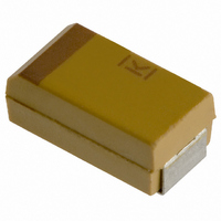
T491B155K025AS Kemet, T491B155K025AS Datasheet - Page 13

T491B155K025AS
Manufacturer Part Number
T491B155K025AS
Description
CAPACITOR TANT 1.5UF 25V 10% SMD
Manufacturer
Kemet
Series
T491r
Type
Moldedr
Datasheet
1.T491B155K025AS.pdf
(100 pages)
Specifications of T491B155K025AS
Capacitance
1.5µF
Voltage - Rated
25V
Tolerance
±10%
Esr (equivalent Series Resistance)
5.000 Ohm
Operating Temperature
-55°C ~ 125°C
Mounting Type
Surface Mount
Package / Case
1210 (3528 Metric)
Size / Dimension
0.138" L x 0.110" W (3.50mm x 2.80mm)
Height
0.075" (1.90mm)
Manufacturer Size Code
B
Features
General Purpose
Lead Free Status / RoHS Status
Contains lead / RoHS non-compliant
Lead Spacing
-
Other names
399-1625-2
Solid tantalum capacitors exhibit no degradation
failure mode during shelf storage and show a
constantly decreasing failure rate (i.e., absence
of any wear out mechanism) during life tests.
This failure rate is dependent upon three impor-
tant application conditions; DC Voltage, ambient
temperature, and circuit impedance. Additional
effects are attributable to the capacitance of the
device and atmospheric and mechanical expo-
sure of the assembled circuit. The 1000 multiplier
at the end converts the failure rate to parts-per-
billion piece-hours. A prediction of the failure rate
can be made using these application conditions
and the formulas and tables listed in MIL-HDBK-
217F (Notice 2).
Base Multiplier: The first multiplier is the base
multiplier (2) established for the capacitor type.
For “CWR-Chips” or surface mount components
the base multiplier is 0.00005, and for “CSR-
Leaded” devices, the base multiplier is 0.00040.
Temperature: The temperature factor is given as
(3). From this formula, it can be seen that the unity
factor, or 1, is derived at an ambient temperature
of +25 C (+298 K), and that at temperatures
below this the multiplier is decreasing and at tem-
peratures above this the multiplier is increasing.
Voltage: The multiplier for application voltage (4)
is a two step process: first, the application volt-
age is compared to 60% of rated voltage, and
then this ratio is raised to an exponential power
of 17 and added to unity. Consider applications
of 50%, 60%, 70%, 80% and 90% of rated volt-
age. The multipliers for these applications would
be 1.045, 2.00, 14.7, 134, and 986, respectively.
From these results it is evident why manufactur-
ers recommend application voltages not to
exceed 50% rated voltages.
Capacitance: There is a factor (5) applied to the
capacitance (in µF) which effectively increases
the failure rate for increasing capacitance
(increases in effective area resulting in increases
in possible faults).
Series Resistance: The series resistance is only
concerned with the resistance per application
bias (ohms per volt) external to the capacitor,
and does not include the ESR as a factor.
Environmental: The environmental factor is
determined by the harshness of the ambient
conditions beyond temperature. An explanation
of these ratings is included in the MIL specifica-
tion and are too extensive to be covered here. In
most cases, this factor is set to ground benign or
G
B
, with the resulting factor equal to “1”.
©KEMET Electronics Corporation, P.O. Box 5928, Greenville, S.C. 29606, (864) 963-6300
SOLID TANTALUM CHIP CAPACITORS
Quality Factor: All of these multipliers are
applied to the established or base failure rate of
the part. The T492 Series is qualified under U.S.
military specification MIL-PRF-55365. Failure
rates as low as 0.001% kHr are available under
this test program.
For series not covered by military specifications,
an internal sampling program is operated by
KEMET Quality Assurance whereby parts are put
on life test at rated voltage for 2000 hours. The
confidence level chosen for the reporting data is
60%. (The cost of sampling each batch would be
prohibitive, and no claim is made to guarantee
the failure rate of each batch.) With this testing
and each new qualification test for new parts, the
average failure rate for all commercial Series lies
between 0.1% and 1.0% per thousand-
piece-hours.
FIT Calculator
All of these factors are gathered into a Windows
based software, available free from the KEMET
web site (www.kemet.com). The “FIT Calculator”
software does all the calculations and look-ups
based on information entered or selected by the
operator. A manual may also be downloaded
from the same web page to explain the controls
and displays The manual as well as a help
screen also detail the environmental conditions.
(1)
(2)
(3)
(4)
(5)
(6)
(7)
S =
V
b
T
C
SR
Q
= 0.00005
= 1.0 • C
=
= exp
=
= Lookup Table
Application-Voltage
(
b T C V SR Q E
Pcs. Tested x Hrs. Tested
Rated-Voltage
[
8.617 • 10
CR ( V)
.023
-0.15
0.6-0.8
0.4-0.6
0.2-0.4
0.1-0.2
CWR
>0.8
<0.1
Pcs. Fail
or 0.0004
-5
(
x 1000
T
1
Amb
0.66
1.0
1.3
2.0
2.7
3.3
CSR
SR
298
E
1
= Lookup Table
) ]
V
=
x 100,000
(
0.6
S
)
17
+ 1
)
11


