MC908JL16CSPE Freescale Semiconductor, MC908JL16CSPE Datasheet - Page 135
MC908JL16CSPE
Manufacturer Part Number
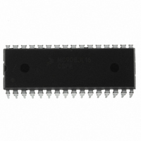
MC908JL16CSPE
Description
IC MCU 16K FLASH 8MHZ 32-SDIP
Manufacturer
Freescale Semiconductor
Series
HC08r
Datasheet
1.MC908JL16CFJER.pdf
(230 pages)
Specifications of MC908JL16CSPE
Core Processor
HC08
Core Size
8-Bit
Speed
8MHz
Connectivity
I²C, SCI
Peripherals
LED, LVD, POR, PWM
Number Of I /o
26
Program Memory Size
16KB (16K x 8)
Program Memory Type
FLASH
Ram Size
512 x 8
Voltage - Supply (vcc/vdd)
2.7 V ~ 5.5 V
Data Converters
A/D 13x10b
Oscillator Type
Internal
Operating Temperature
-40°C ~ 85°C
Package / Case
32-SDIP (0.400", 10.16mm)
Controller Family/series
HC08
No. Of I/o's
26
Ram Memory Size
512Byte
Cpu Speed
8MHz
No. Of Timers
2
Embedded Interface Type
I2C, SCI
Rohs Compliant
Yes
Processor Series
HC08JL
Core
HC08
Data Bus Width
8 bit
Data Ram Size
512 B
Interface Type
SCI
Maximum Clock Frequency
16 MHz
Number Of Programmable I/os
26
Number Of Timers
4
Operating Supply Voltage
2.7 V to 5.5 V
Maximum Operating Temperature
+ 85 C
Mounting Style
Through Hole
Development Tools By Supplier
FSICEBASE, DEMO908JL16E, M68CBL05CE
Minimum Operating Temperature
- 40 C
On-chip Adc
10 bit, 13 Channel
For Use With
DEMO908JL16E - BOARD DEMO FOR MC908JL16
Lead Free Status / RoHS Status
Lead free / RoHS Compliant
Eeprom Size
-
Lead Free Status / Rohs Status
Details
Available stocks
Company
Part Number
Manufacturer
Quantity
Price
Company:

Part Number:
MC908JL16CSPE
Manufacturer:
SONY
Quantity:
1 560
Part Number:
MC908JL16CSPE
Manufacturer:
FREESCALE
Quantity:
20 000


9.8.4 ADC10 Clock Register (ADCLK)
This register selects the clock frequency for the ADC10 and the modes of operation.
ADLPC — ADC10 Low-Power Configuration Bit
ADIV[1:0] — ADC10 Clock Divider Bits
ADICLK — Input Clock Select Bit
MODE[1:0] — 10- or 8-Bit or External-Triggered Mode Selection
Freescale Semiconductor
ADLPC controls the speed and power configuration of the successive approximation converter. This
is used to optimize power consumption when higher sample rates are not required.
ADIV1 and ADIV0 select the divide ratio used by the ADC10 to generate the internal clock ADCK.
Table 9-3
If ACLKEN is clear, ADICLK selects either the bus clock or an alternate clock source as the input clock
source to generate the internal clock ADCK. If the alternate clock source is less than the minimum
clock speed, use the internally-generated bus clock as the clock source. As long as the internal clock
ADCK, which is equal to the selected input clock divided by ADIV, is at a frequency (f
the minimum and maximum clock speeds (considering ALPC), correct operation can be guaranteed.
This bit selects between 10- or 8-bit operation. The successive approximation converter generates a
result which is rounded to 8- or 10-bit value based on the mode selection. This rounding process sets
the transfer function to transition at the midpoint between the ideal code voltages, causing a
quantization error of 1/2
Reset returns 8-bit mode.
1 = Low-power configuration: The power is reduced at the expense of maximum clock speed.
0 = High-speed configuration
1 = The internal bus clock is selected as the input clock source
0 = The alternate clock source IS SELECTED
shows the available clock configurations.
Address:
MODE1
Reset:
Read:
Write:
0
0
1
1
ADLPC
$003F
Bit 7
ADIV1
0
MODE0
0
0
1
1
LSB
Figure 9-7. ADC10 Clock Register (ADCLK)
0
1
0
1
.
ADIV1
Table 9-3. ADC10 Clock Divide Ratio
6
0
ADIV0
MC68HC908JL16 Data Sheet, Rev. 1.1
0
1
0
1
8-bit, right-justified, ADCSC write-triggered mode enabled
10-bit, right-justified, ADCSC write-triggered mode enabled
Reserved.
10-bit, right-justified, external triggered mode enabled
Table 9-4. Mode Selection
ADIV0
5
0
Divide Ratio (ADIV)
ADICLK
4
0
1
2
4
8
MODE1
3
0
Mode
MODE0
Input clock ÷ 1
Input clock ÷ 2
Input clock ÷ 4
Input clock ÷ 8
Clock Rate
2
0
ADLSMP
1
0
ACLKEN
Bit 0
0
ADCK
) between
Registers
135
Related parts for MC908JL16CSPE
Image
Part Number
Description
Manufacturer
Datasheet
Request
R

Part Number:
Description:
Manufacturer:
Freescale Semiconductor, Inc
Datasheet:
Part Number:
Description:
Manufacturer:
Freescale Semiconductor, Inc
Datasheet:
Part Number:
Description:
Manufacturer:
Freescale Semiconductor, Inc
Datasheet:
Part Number:
Description:
Manufacturer:
Freescale Semiconductor, Inc
Datasheet:
Part Number:
Description:
Manufacturer:
Freescale Semiconductor, Inc
Datasheet:
Part Number:
Description:
Manufacturer:
Freescale Semiconductor, Inc
Datasheet:
Part Number:
Description:
Manufacturer:
Freescale Semiconductor, Inc
Datasheet:
Part Number:
Description:
Manufacturer:
Freescale Semiconductor, Inc
Datasheet:
Part Number:
Description:
Manufacturer:
Freescale Semiconductor, Inc
Datasheet:
Part Number:
Description:
Manufacturer:
Freescale Semiconductor, Inc
Datasheet:
Part Number:
Description:
Manufacturer:
Freescale Semiconductor, Inc
Datasheet:
Part Number:
Description:
Manufacturer:
Freescale Semiconductor, Inc
Datasheet:
Part Number:
Description:
Manufacturer:
Freescale Semiconductor, Inc
Datasheet:
Part Number:
Description:
Manufacturer:
Freescale Semiconductor, Inc
Datasheet:
Part Number:
Description:
Manufacturer:
Freescale Semiconductor, Inc
Datasheet: