MC908JL16CSPE Freescale Semiconductor, MC908JL16CSPE Datasheet - Page 215
MC908JL16CSPE
Manufacturer Part Number
MC908JL16CSPE
Description
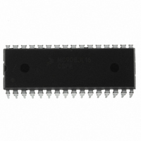
IC MCU 16K FLASH 8MHZ 32-SDIP
Manufacturer
Freescale Semiconductor
Series
HC08r
Datasheet
1.MC908JL16CFJER.pdf
(230 pages)
Specifications of MC908JL16CSPE
Core Processor
HC08
Core Size
8-Bit
Speed
8MHz
Connectivity
I²C, SCI
Peripherals
LED, LVD, POR, PWM
Number Of I /o
26
Program Memory Size
16KB (16K x 8)
Program Memory Type
FLASH
Ram Size
512 x 8
Voltage - Supply (vcc/vdd)
2.7 V ~ 5.5 V
Data Converters
A/D 13x10b
Oscillator Type
Internal
Operating Temperature
-40°C ~ 85°C
Package / Case
32-SDIP (0.400", 10.16mm)
Controller Family/series
HC08
No. Of I/o's
26
Ram Memory Size
512Byte
Cpu Speed
8MHz
No. Of Timers
2
Embedded Interface Type
I2C, SCI
Rohs Compliant
Yes
Processor Series
HC08JL
Core
HC08
Data Bus Width
8 bit
Data Ram Size
512 B
Interface Type
SCI
Maximum Clock Frequency
16 MHz
Number Of Programmable I/os
26
Number Of Timers
4
Operating Supply Voltage
2.7 V to 5.5 V
Maximum Operating Temperature
+ 85 C
Mounting Style
Through Hole
Development Tools By Supplier
FSICEBASE, DEMO908JL16E, M68CBL05CE
Minimum Operating Temperature
- 40 C
On-chip Adc
10 bit, 13 Channel
For Use With
DEMO908JL16E - BOARD DEMO FOR MC908JL16
Lead Free Status / RoHS Status
Lead free / RoHS Compliant
Eeprom Size
-
Lead Free Status / Rohs Status
Details
Available stocks
Company
Part Number
Manufacturer
Quantity
Price
Company:

Part Number:
MC908JL16CSPE
Manufacturer:
SONY
Quantity:
1 560
Part Number:
MC908JL16CSPE
Manufacturer:
FREESCALE
Quantity:
20 000


Freescale Semiconductor
Operating frequency
Bus free time
Repeated start hold time.
Repeated start setup time.
Stop setup time
Hold time
Setup time
Clock low time-out
Clock low
Clock high
Slave clock low extend time
Master clock low extend time
Fall time
Rise time
1. Devices participating in a transfer will timeout when any clock low exceeds the value of T
2. T
3. T
4. T
5. Rise and fall time is defined as follows: T
that have detected a timeout condition must reset the communication no later than T
value specified must be adhered to by both a master and a slave as it incorporates the cumulative limit for both a master
(10 ms) and a slave (25 ms).
Software should turn-off the MMIIC module to release the SDA and SCL lines.
to the stop. If a slave device exceeds this time, it is expected to release both its clock and data lines and reset itself.
defined from start-to-ack, ack-to-ack, or ack-to-stop.
HIGH MAX
LOW.SEXT
LOW.MEXT
Characteristic
provides a simple guaranteed method for devices to detect the idle conditions.
is the cumulative time a slave device is allowed to extend the clock cycles in one message from the initial start
is the cumulative time a master device is allowed to extend its clock cycles within each byte of a message as
Table 17-13. MMIIC Interface Input/Output Signal Timing
t
t
LOW.MEXT
LOW.SEXT
Symbol
t
t
t
t
t
t
TIMEOUT
SU.STO
HD.STA
HD.DAT
SU.DAT
SU.STA
t
f
t
t
HIGH
SMB
LOW
BUF
t
t
R
F
MC68HC908JL16 Data Sheet, Rev. 1.1
R
= (V
ILMAX
Min
300
250
4.7
4.7
4.0
4.7
4.0
10
4.0
25
—
—
—
—
– 0.15) to (V
Typ
—
—
—
—
—
—
—
—
—
—
—
—
—
—
1000
IHMIN
Max
100
300
35
—
—
—
—
—
—
—
—
25
10
+ 0.15), T
Unit
kHz
ms
ms
ms
µs
µs
µs
µs
µs
µs
ns
ns
ns
ns
F
MMIIC operating frequency
Bus free time between STOP and
START condition
Hold time after (repeated) START
condition. After this period, the first
clock is generated.
Repeated START condition setup time.
Stop condition setup time.
Data hold time.
Data setup time.
Clock low time-out.
Clock low period
Clock high period.
Cumulative clock low extend time (slave
device)
Cumulative clock low extend time
(master device)
Clock/Data Fall Time
Clock/Data Rise Time
= 0.9×V
TIMEOUT
MMIIC Electrical Characteristics
(3)
TIMEOUT
DD
max of 35ms. The maximum
to (V
Comments
(4)
min. of 25ms. Devices
ILMAX
(2)
(1)
(5)
(5)
– 0.15).
215
Related parts for MC908JL16CSPE
Image
Part Number
Description
Manufacturer
Datasheet
Request
R

Part Number:
Description:
Manufacturer:
Freescale Semiconductor, Inc
Datasheet:
Part Number:
Description:
Manufacturer:
Freescale Semiconductor, Inc
Datasheet:
Part Number:
Description:
Manufacturer:
Freescale Semiconductor, Inc
Datasheet:
Part Number:
Description:
Manufacturer:
Freescale Semiconductor, Inc
Datasheet:
Part Number:
Description:
Manufacturer:
Freescale Semiconductor, Inc
Datasheet:
Part Number:
Description:
Manufacturer:
Freescale Semiconductor, Inc
Datasheet:
Part Number:
Description:
Manufacturer:
Freescale Semiconductor, Inc
Datasheet:
Part Number:
Description:
Manufacturer:
Freescale Semiconductor, Inc
Datasheet:
Part Number:
Description:
Manufacturer:
Freescale Semiconductor, Inc
Datasheet:
Part Number:
Description:
Manufacturer:
Freescale Semiconductor, Inc
Datasheet:
Part Number:
Description:
Manufacturer:
Freescale Semiconductor, Inc
Datasheet:
Part Number:
Description:
Manufacturer:
Freescale Semiconductor, Inc
Datasheet:
Part Number:
Description:
Manufacturer:
Freescale Semiconductor, Inc
Datasheet:
Part Number:
Description:
Manufacturer:
Freescale Semiconductor, Inc
Datasheet:
Part Number:
Description:
Manufacturer:
Freescale Semiconductor, Inc
Datasheet: