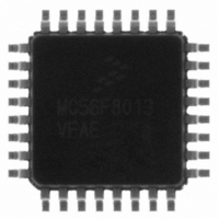
MC56F8013VFAE Freescale Semiconductor, MC56F8013VFAE Datasheet - Page 31

MC56F8013VFAE
Manufacturer Part Number
MC56F8013VFAE
Description
IC DIGITAL SIGNAL CTLR 32-LQFP
Manufacturer
Freescale Semiconductor
Series
56F8xxxr
Datasheet
1.MC56F8013VFAE.pdf
(126 pages)
Specifications of MC56F8013VFAE
Core Processor
56800
Core Size
16-Bit
Speed
32MHz
Connectivity
I²C, SCI, SPI
Peripherals
POR, PWM, WDT
Number Of I /o
26
Program Memory Size
16KB (8K x 16)
Program Memory Type
FLASH
Ram Size
2K x 16
Voltage - Supply (vcc/vdd)
3 V ~ 3.6 V
Data Converters
A/D 6x12b
Oscillator Type
Internal
Operating Temperature
-40°C ~ 105°C
Package / Case
32-LQFP
Product
DSCs
Data Bus Width
16 bit
Processor Series
MC56F80xx
Core
56800E
Numeric And Arithmetic Format
Fixed-Point
Device Million Instructions Per Second
32 MIPs
Maximum Clock Frequency
32 MHz
Number Of Programmable I/os
26
Data Ram Size
4 KB
Operating Supply Voltage
3.3 V
Maximum Operating Temperature
+ 105 C
Mounting Style
SMD/SMT
Data Rom Size
16 KB
Development Tools By Supplier
MC56F8037EVM, DEMO56F8014-EE, DEMO56F8013-EE
Interface Type
SCI, SPI, I2C
Minimum Operating Temperature
- 40 C
For Use With
CPA56F8013 - BOARD SOCKET FOR MC56F8013APMOTOR56F8000E - KIT DEMO MOTOR CTRL SYSTEMDEMO56F8013-EE - BOARD DEMO FOR 56F8013
Lead Free Status / RoHS Status
Lead free / RoHS Compliant
Eeprom Size
-
Lead Free Status / Rohs Status
Lead free / RoHS Compliant
Available stocks
Company
Part Number
Manufacturer
Quantity
Price
Company:
Part Number:
MC56F8013VFAE
Manufacturer:
FREESCAL
Quantity:
210
Company:
Part Number:
MC56F8013VFAE
Manufacturer:
Freescale Semiconductor
Quantity:
10 000
Part Number:
MC56F8013VFAE
Manufacturer:
FREESCALE
Quantity:
20 000
Company:
Part Number:
MC56F8013VFAEN
Manufacturer:
Freescale
Quantity:
52
Part Number:
MC56F8013VFAEN
Manufacturer:
FREESCALE
Quantity:
20 000
Company:
Part Number:
MC56F8013VFAER2
Manufacturer:
Freescale Semiconductor
Quantity:
10 000
4.3 Program Map
The Program Memory map is shown in
Freescale Semiconductor
1. Two words are allocated for each entry in the vector table. This does not allow the full address range to be referenced
2. If the VBA is set to the reset value, the first two locations of the vector table will overlay the chip reset addresses.
Timer
Timer
ADC
ADC
ADC
PWM
PWM
SWILP
Peripheral
from the vector table, providing only 19 bits of address.
40
41
42
45
38
39
43
44
Number
Vector
Table 4-2 Interrupt Vector Table Contents
1. All addresses are 16-bit Word addresses.
2. This RAM is shared with Data space starting at address X: $00 0000;
P: $FF FFFF
P: $00 8800
P: $00 87FF
P: $00 8000
P: $00 7FFF
P: $00 2000
P: $00 1FFF
P: $00 0000
Begin/End Address
see
0-2
0-2
0-2
0-2
0-2
-1
0-2
0-2
Table 4-3 Program Memory Map for 56F8013
Priority
Level
Figure
4-1.
P:$4C
P:$4E
P:$50
P:$52
P:$54
P:$56
P:$58
P:$5A
56F8013/56F8011 Data Sheet, Rev. 12
Vector Base
Address +
Table
RESERVED
On-Chip RAM
4KB
RESERVED
Internal Program Flash
16KB
Cop Reset Address = $00 0002
Boot Location = $00 0000
4-3.
ADCA Conversion Complete
ADCB Conversion Complete
ADC Zero Crossing or Limit Error
Reload PWM
Timer Channel 2
Timer Channel 3
PWM Fault
SW Interrupt Low Priority
Memory Allocation
2
Interrupt Function
1
(Continued)
1
Program Map
31


