PIC16LF707-I/P Microchip Technology, PIC16LF707-I/P Datasheet - Page 105
PIC16LF707-I/P
Manufacturer Part Number
PIC16LF707-I/P
Description
MCU 8BIT 14KB FLASH 5.5V 40PDIP
Manufacturer
Microchip Technology
Series
PIC® XLP™ 16Fr
Specifications of PIC16LF707-I/P
Core Size
8-Bit
Program Memory Size
14KB (8K x 14)
Peripherals
Brown-out Detect/Reset, POR, PWM, WDT
Core Processor
PIC
Speed
20MHz
Connectivity
I²C, SPI, UART/USART
Number Of I /o
36
Program Memory Type
FLASH
Ram Size
363 x 8
Voltage - Supply (vcc/vdd)
1.8 V ~ 3.6 V
Data Converters
A/D 14x8b
Oscillator Type
Internal
Operating Temperature
-40°C ~ 85°C
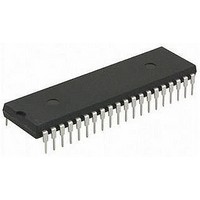
Package / Case
40-DIP (0.600", 15.24mm)
Controller Family/series
PIC16LF
No. Of I/o's
36
Ram Memory Size
363Byte
Cpu Speed
20MHz
No. Of Timers
6
Processor Series
PIC16LF
Core
PIC
Data Bus Width
8 bit
Data Ram Size
368 B
Interface Type
I2C, SPI, AUSART
Maximum Clock Frequency
20 MHz
Number Of Programmable I/os
36
Number Of Timers
4
Operating Supply Voltage
1.8 V to 3.6 V
Maximum Operating Temperature
+ 85 C
Mounting Style
Through Hole
3rd Party Development Tools
52715-96, 52716-328, 52717-734
Development Tools By Supplier
PG164130, DV164035, DV244005, DV164005, PG164120, ICE2000
Minimum Operating Temperature
- 40 C
On-chip Adc
8 bit, 14 Channel
On-chip Dac
5 bit
Lead Free Status / RoHS Status
Lead free / RoHS Compliant
Eeprom Size
-
Lead Free Status / Rohs Status
Details
Available stocks
Company
Part Number
Manufacturer
Quantity
Price
Company:

Part Number:
PIC16LF707-I/PT
Manufacturer:
Microchip Technology
Quantity:
10 000


13.8
Timer1/3 can only operate during Sleep when setup in
Asynchronous Counter mode. In this mode, an external
crystal or clock source can be used to increment the
counter. To set up the timer to wake the device:
• TMRxON bit of the TxCON register must be set
• TMRxIE bit of the PIEx register must be set
• PEIE bit of the INTCON register must be set
• TxSYNC bit of the TxCON register must be set
• TMRxCS bits of the TxCON register must be
• T1OSCEN bit of the T1CON register must be
• TMRxGIE bit of the TxGCON register must be
The device will wake-up on an overflow and execute
the next instructions. If the GIE bit of the INTCON
register is set, the device will call the Interrupt Service
Routine (0004h).
13.9
The CCP module uses the TMR1H:TMR1L register
pair as the time base when operating in Capture or
Compare mode.
FIGURE 13-2:
2010 Microchip Technology Inc.
configured
configured
configured
Note 1: Arrows indicate counter increments.
TxCKI = 1
when TMR1/3
Enabled
TxCKI = 0
when TMR1/3
Enabled
2: In Counter mode, a falling edge must be registered by the counter prior to the first incrementing rising edge of the clock.
Timer1/3 Operation During Sleep
CCP Capture/Compare Time Base
(Timer1 Only)
TIMER1/TIMER3 INCREMENTING EDGE
Preliminary
PIC16F707/PIC16LF707
In Capture mode, the value in the TMR1H:TMR1L
register pair is copied into the CCPR1H:CCPR1L
register pair on a configured event.
In Compare mode, an event is triggered when the value
CCPR1H:CCPR1L register pair matches the value in
the TMR1H:TMR1L register pair. This event can be a
Special Event Trigger.
For more information, see Section 17.0 “Capture/
Compare/PWM (CCP) Module”.
13.10 CCP Special Event Trigger
When the CCP is configured to trigger a special event,
the trigger will clear the TMR1H:TMR1L register pair.
This special event does not cause a Timer1 interrupt.
The CCP module may still be configured to generate a
CCP interrupt.
In this mode of operation, the CCPR1H:CCPR1L
register pair becomes the period register for Timer1.
Timer1 should be synchronized to the F
the Special Event Trigger. Asynchronous operation of
Timer1 can cause a Special Event Trigger to be
missed.
In the event that a write to TMR1H or TMR1L coincides
with a Special Event Trigger from the CCP, the write will
take precedence.
For more information, see Section 17.2.4 “Special
Event Trigger”.
(Timer1 only)
DS41418A-page 105
OSC
/4 to utilize
Related parts for PIC16LF707-I/P
Image
Part Number
Description
Manufacturer
Datasheet
Request
R

Part Number:
Description:
Manufacturer:
Microchip Technology Inc.
Datasheet:
Part Number:
Description:
Manufacturer:
Microchip Technology Inc.
Datasheet:
Part Number:
Description:
Manufacturer:
Microchip Technology Inc.
Datasheet:
Part Number:
Description:
Manufacturer:
Microchip Technology Inc.
Datasheet:
Part Number:
Description:
Manufacturer:
Microchip Technology Inc.
Datasheet:
Part Number:
Description:
Manufacturer:
Microchip Technology Inc.
Datasheet:
Part Number:
Description:
Manufacturer:
Microchip Technology Inc.
Datasheet:
Part Number:
Description:
Manufacturer:
Microchip Technology Inc.
Datasheet: