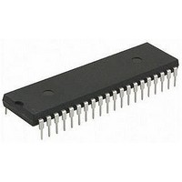
PIC16LF707-I/P Microchip Technology, PIC16LF707-I/P Datasheet - Page 49

PIC16LF707-I/P
Manufacturer Part Number
PIC16LF707-I/P
Description
MCU 8BIT 14KB FLASH 5.5V 40PDIP
Manufacturer
Microchip Technology
Series
PIC® XLP™ 16Fr
Specifications of PIC16LF707-I/P
Core Size
8-Bit
Program Memory Size
14KB (8K x 14)
Peripherals
Brown-out Detect/Reset, POR, PWM, WDT
Core Processor
PIC
Speed
20MHz
Connectivity
I²C, SPI, UART/USART
Number Of I /o
36
Program Memory Type
FLASH
Ram Size
363 x 8
Voltage - Supply (vcc/vdd)
1.8 V ~ 3.6 V
Data Converters
A/D 14x8b
Oscillator Type
Internal
Operating Temperature
-40°C ~ 85°C
Package / Case
40-DIP (0.600", 15.24mm)
Controller Family/series
PIC16LF
No. Of I/o's
36
Ram Memory Size
363Byte
Cpu Speed
20MHz
No. Of Timers
6
Processor Series
PIC16LF
Core
PIC
Data Bus Width
8 bit
Data Ram Size
368 B
Interface Type
I2C, SPI, AUSART
Maximum Clock Frequency
20 MHz
Number Of Programmable I/os
36
Number Of Timers
4
Operating Supply Voltage
1.8 V to 3.6 V
Maximum Operating Temperature
+ 85 C
Mounting Style
Through Hole
3rd Party Development Tools
52715-96, 52716-328, 52717-734
Development Tools By Supplier
PG164130, DV164035, DV244005, DV164005, PG164120, ICE2000
Minimum Operating Temperature
- 40 C
On-chip Adc
8 bit, 14 Channel
On-chip Dac
5 bit
Lead Free Status / RoHS Status
Lead free / RoHS Compliant
Eeprom Size
-
Lead Free Status / Rohs Status
Details
Available stocks
Company
Part Number
Manufacturer
Quantity
Price
Company:
Part Number:
PIC16LF707-I/PT
Manufacturer:
Microchip Technology
Quantity:
10 000
- Current page: 49 of 284
- Download datasheet (3Mb)
5.0
The PIC16F707 has an internal Low Dropout Regulator
(LDO) which provides operation above 3.6V. The LDO
regulates a voltage for the internal device logic while
permitting the V
voltage. There is no user enable/disable control
available for the LDO, it is always active. The
PIC16LF707 operates at a maximum V
does not incorporate an LDO.
A device I/O pin may be configured as the LDO voltage
output, identified as the V
required, an external low-ESR capacitor may be
connected to the V
stability.
The VCAPEN<1:0> bits of Configuration Word 2
determines which pin is assigned as the V
Refer to Table 5-1.
TABLE 5-1:
TABLE 5-2:
2010 Microchip Technology Inc.
CONFIG2
Legend:
Note 1:
Name
VCAPEN<1:0>
LOW DROPOUT (LDO)
VOLTAGE REGULATOR
— = unimplemented locations read as ‘0’. Shaded cells are not used by LDO.
PIC16F707 only.
00
01
10
11
Bits
13:8
7:0
DD
VCAPEN<1:0> SELECT BITS
SUMMARY OF CONFIGURATION WORD WITH LDO
and I/O pins to operate at a higher
Bit -/7
CAP
—
—
pin for additional regulator
CAP
Bit -/6
—
—
pin. Although not
No V
RA0
RA5
RA6
Pin
DD
VCAPEN1
CAP
Bit 13/5
of 3.6V and
—
CAP
(1)
pin.
Preliminary
VCAPEN0
Bit 12/4
—
PIC16F707/PIC16LF707
(1)
On power-up, the external capacitor will load the LDO
voltage regulator. To prevent erroneous operation, the
device is held in Reset while a constant current source
charges the external capacitor. After the cap is fully
charged, the device is released from Reset. For more
information on recommended capacitor values and the
constant current rate, refer to the LDO Regulator
Characteristics Table in Section 25.0 “Electrical
Specifications”.
Bit 11/3
—
—
Bit 10/2
—
—
Bit 9/1
—
—
Bit 8/0
DS41418A-page 49
—
—
Register
on Page
76
Related parts for PIC16LF707-I/P
Image
Part Number
Description
Manufacturer
Datasheet
Request
R

Part Number:
Description:
Manufacturer:
Microchip Technology Inc.
Datasheet:

Part Number:
Description:
Manufacturer:
Microchip Technology Inc.
Datasheet:

Part Number:
Description:
Manufacturer:
Microchip Technology Inc.
Datasheet:

Part Number:
Description:
Manufacturer:
Microchip Technology Inc.
Datasheet:

Part Number:
Description:
Manufacturer:
Microchip Technology Inc.
Datasheet:

Part Number:
Description:
Manufacturer:
Microchip Technology Inc.
Datasheet:

Part Number:
Description:
Manufacturer:
Microchip Technology Inc.
Datasheet:

Part Number:
Description:
Manufacturer:
Microchip Technology Inc.
Datasheet:


