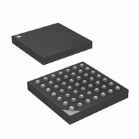
ATXMEGA32A4-CUR Atmel, ATXMEGA32A4-CUR Datasheet - Page 281

ATXMEGA32A4-CUR
Manufacturer Part Number
ATXMEGA32A4-CUR
Description
MCU AVR 32+4 FLASH 49VFBGA
Manufacturer
Atmel
Series
AVR® XMEGAr
Specifications of ATXMEGA32A4-CUR
Core Processor
AVR
Core Size
8/16-Bit
Speed
32MHz
Connectivity
I²C, IrDA, SPI, UART/USART
Peripherals
Brown-out Detect/Reset, DMA, POR, PWM, WDT
Number Of I /o
34
Program Memory Size
32KB (16K x 16)
Program Memory Type
FLASH
Eeprom Size
2K x 8
Ram Size
4K x 8
Voltage - Supply (vcc/vdd)
1.6 V ~ 3.6 V
Data Converters
A/D 12x12b, D/A 2x12b
Oscillator Type
Internal
Operating Temperature
-40°C ~ 85°C
Package / Case
49-VFBGA
For Use With
ATAVRONEKIT - KIT AVR/AVR32 DEBUGGER/PROGRMMRATSTK600 - DEV KIT FOR AVR/AVR32770-1007 - ISP 4PORT ATMEL AVR MCU SPI/JTAG770-1004 - ISP 4PORT FOR ATMEL AVR MCU SPI
Lead Free Status / RoHS Status
Lead free / RoHS Compliant
Available stocks
Company
Part Number
Manufacturer
Quantity
Price
- Current page: 281 of 445
- Download datasheet (6Mb)
24.11.3
24.11.4
24.11.5
8077H–AVR–12/09
REFRESH - SDRAM Refresh Period Register
INITDLY - SDRAM Initialization Delay Register
SDRAMCTRLB - SDRAM Control Register B
• Bit 15:10 - Reserved
These bits are reserved and will always be read as zero.
• Bit 9:0 - REFRESH[9:0]: SDRAM Refresh Period
This register sets the refresh period as a number of Peripheral 2x clock (CLK
EBI is busy with another external memory access at time of refresh, up to 4 refresh will be
remembered and given at the first available time.
• Bit 15:14 - Reserved
These bits are reserved and will always be read as zero.
• Bit 13:0 - INITDLY[13:0]: SDRAM Initialization Delay
This register is used to delay the initialisation sequence after the controller is enabled until all
voltages are stabilized and the SDRAM clock has been running long enough to take the SDRAM
chip through its initialisation sequence. The initialisation sequence includes pre-charge all banks
to their idle state issuing an auto-refresh cycle and then loading the mode register. The setting in
this register is as a number of Peripheral 2x clock cycles.
Bit
+0x04
+0x05
Read/Write
Initial Value
Bit
+0x06
+0x07
Read/Write
Initial Value
Bit
+0x08
Read/Write
Initial Value
R/W
R/W
R/W
15
15
R
R
7
0
0
7
0
0
7
0
-
-
MRDLY[1:0]
R/W
R/W
R/W
14
14
R
R
6
0
0
6
0
0
6
0
-
-
R/W
R/W
R/W
R/W
13
13
R
5
0
5
0
0
5
0
0
-
ROWCYCDLY[2:0]
R/W
R/W
R/W
R/W
12
12
R
4
0
4
0
0
4
0
0
REFRESH[7:0]
-
INITDLY[7:0]
R/W
R/W
R/W
R/W
11
11
R
3
0
3
0
0
3
0
0
-
INITDLY[9:8]
R/W
R/W
R/W
R/W
10
10
R
2
0
2
0
0
2
0
0
-
RPDLY[2:0]
R/W
R/W
R/W
R/W
R/W
REFRESH[9:8]
1
0
1
9
0
0
1
9
0
0
R/W
R/W
R/W
R/W
R/W
0
0
0
8
0
0
0
8
0
0
XMEGA A
PER
) cycles. If the
SDRAMCTRLB
REFRESHL
REFRESHH
INITDLYL
INITDLYH
281
Related parts for ATXMEGA32A4-CUR
Image
Part Number
Description
Manufacturer
Datasheet
Request
R

Part Number:
Description:
DEV KIT FOR AVR/AVR32
Manufacturer:
Atmel
Datasheet:

Part Number:
Description:
INTERVAL AND WIPE/WASH WIPER CONTROL IC WITH DELAY
Manufacturer:
ATMEL Corporation
Datasheet:

Part Number:
Description:
Low-Voltage Voice-Switched IC for Hands-Free Operation
Manufacturer:
ATMEL Corporation
Datasheet:

Part Number:
Description:
MONOLITHIC INTEGRATED FEATUREPHONE CIRCUIT
Manufacturer:
ATMEL Corporation
Datasheet:

Part Number:
Description:
AM-FM Receiver IC U4255BM-M
Manufacturer:
ATMEL Corporation
Datasheet:

Part Number:
Description:
Monolithic Integrated Feature Phone Circuit
Manufacturer:
ATMEL Corporation
Datasheet:

Part Number:
Description:
Multistandard Video-IF and Quasi Parallel Sound Processing
Manufacturer:
ATMEL Corporation
Datasheet:

Part Number:
Description:
High-performance EE PLD
Manufacturer:
ATMEL Corporation
Datasheet:

Part Number:
Description:
8-bit Flash Microcontroller
Manufacturer:
ATMEL Corporation
Datasheet:

Part Number:
Description:
2-Wire Serial EEPROM
Manufacturer:
ATMEL Corporation
Datasheet:


