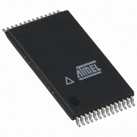
ATMEGA8HVA-4TU Atmel, ATMEGA8HVA-4TU Datasheet - Page 43

ATMEGA8HVA-4TU
Manufacturer Part Number
ATMEGA8HVA-4TU
Description
MCU AVR 8K FLASH 4MHZ 28-TSOP
Manufacturer
Atmel
Series
AVR® ATmegar
Datasheet
1.ATMEGA16HVA-4CKU.pdf
(196 pages)
Specifications of ATMEGA8HVA-4TU
Core Processor
AVR
Core Size
8-Bit
Speed
4MHz
Connectivity
SPI
Peripherals
Brown-out Detect/Reset, POR, PWM, WDT
Number Of I /o
7
Program Memory Size
8KB (4K x 16)
Program Memory Type
FLASH
Eeprom Size
256 x 8
Ram Size
512 x 8
Voltage - Supply (vcc/vdd)
1.8 V ~ 9 V
Data Converters
A/D 5x12b
Oscillator Type
External
Operating Temperature
-20°C ~ 85°C
Package / Case
28-TSOP
For Use With
ATSTK600 - DEV KIT FOR AVR/AVR32ATSTK500 - PROGRAMMER AVR STARTER KIT
Lead Free Status / RoHS Status
Lead free / RoHS Compliant
- Current page: 43 of 196
- Download datasheet (3Mb)
Figure 11-2. Normal Start-up Sequence in Power-off.
8024A–AVR–04/08
1. The charger voltage pulls the BATT pin above the Power-on Threshold Voltage (V
2. When V
3. The internal reset is held high after POR reset goes low for a time given by t
4. As soon as the internal reset goes low, the chip will start operating in DUVR mode (for
VREG starts to rise. The POR reset will go high while VREG is rising and initiate the
internal reset state of the chip. The external FETs are initially switched off.
”System Control and Reset” on page
isters will be reset to their default values. The VREG and BOD levels are both referenced
to the VREF voltage. In reset all these voltage levels will therefore have default values.
Both FETs are switched completely off in this state.
details on DUVR mode, see
on page 137
gate voltage of the Charge FET to get a voltage at the VFET pin given by the VFET level
specified in
that DUVR mode will only regulate the VFET voltage as long as the cell voltage is lower
than the VFET_DUVR level. For high cell voltages, DUVR mode will not have any impact.
DUVR mode may be disabled by SW as soon as the chip enters ACTIVE mode.
BATT
Table 29-5 on page
rises above V
and application note AVR354). In DUVR mode the FET driver controls the
POT
”DUVR – Deep Under-Voltage Recovery Mode operation”
, ATmega8HVA/16HVA turns on the Voltage Regulator and
170. This causes the BATT voltage to decrease. Note
41. While the chip is in reset, VREF calibration reg-
4/8/16/32/64/128/256/512 ms
ATmega8HVA/16HVA
TOUT
, see
POT
).
43
Related parts for ATMEGA8HVA-4TU
Image
Part Number
Description
Manufacturer
Datasheet
Request
R

Part Number:
Description:
IC AVR MCU 2.4GHZ XCEIVER 64QFN
Manufacturer:
Atmel
Datasheet:

Part Number:
Description:
Manufacturer:
Atmel
Datasheet:

Part Number:
Description:
MCU ATMEGA644/AT86RF230 40-DIP
Manufacturer:
Atmel
Datasheet:

Part Number:
Description:
BUNDLE ATMEGA644P/AT86RF230 QFN
Manufacturer:
Atmel
Datasheet:

Part Number:
Description:
BUNDLE ATMEGA644P/AT86RF230 TQFP
Manufacturer:
Atmel
Datasheet:

Part Number:
Description:
MCU ATMEGA1281/AT86RF230 64-TQFP
Manufacturer:
Atmel
Datasheet:

Part Number:
Description:
MCU ATMEGA1280/AT86RF230 100TQFP
Manufacturer:
Atmel
Datasheet:

Part Number:
Description:
BUNDLE ATMEGA1280/AT86RF100-TQFP
Manufacturer:
Atmel
Datasheet:

Part Number:
Description:
BUNDLE ATMEGA2560V/AT86RF230-ZU
Manufacturer:
Atmel
Datasheet:

Part Number:
Description:
MCU ATMEGA2561/AT86RF230 64-TQFP
Manufacturer:
Atmel
Datasheet:

Part Number:
Description:
INTERVAL AND WIPE/WASH WIPER CONTROL IC WITH DELAY
Manufacturer:
ATMEL Corporation
Datasheet:

Part Number:
Description:
Low-Voltage Voice-Switched IC for Hands-Free Operation
Manufacturer:
ATMEL Corporation
Datasheet:

Part Number:
Description:
MONOLITHIC INTEGRATED FEATUREPHONE CIRCUIT
Manufacturer:
ATMEL Corporation
Datasheet:

Part Number:
Description:
AM-FM Receiver IC U4255BM-M
Manufacturer:
ATMEL Corporation
Datasheet:


