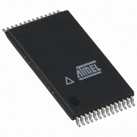
ATMEGA8HVA-4TU Atmel, ATMEGA8HVA-4TU Datasheet - Page 84

ATMEGA8HVA-4TU
Manufacturer Part Number
ATMEGA8HVA-4TU
Description
MCU AVR 8K FLASH 4MHZ 28-TSOP
Manufacturer
Atmel
Series
AVR® ATmegar
Datasheet
1.ATMEGA16HVA-4CKU.pdf
(196 pages)
Specifications of ATMEGA8HVA-4TU
Core Processor
AVR
Core Size
8-Bit
Speed
4MHz
Connectivity
SPI
Peripherals
Brown-out Detect/Reset, POR, PWM, WDT
Number Of I /o
7
Program Memory Size
8KB (4K x 16)
Program Memory Type
FLASH
Eeprom Size
256 x 8
Ram Size
512 x 8
Voltage - Supply (vcc/vdd)
1.8 V ~ 9 V
Data Converters
A/D 5x12b
Oscillator Type
External
Operating Temperature
-20°C ~ 85°C
Package / Case
28-TSOP
For Use With
ATSTK600 - DEV KIT FOR AVR/AVR32ATSTK500 - PROGRAMMER AVR STARTER KIT
Lead Free Status / RoHS Status
Lead free / RoHS Compliant
- Current page: 84 of 196
- Download datasheet (3Mb)
17.7
84
Output Compare Unit
ATmega8HVA/16HVA
cleared by software (writing a logical one to the I/O bit location). For measuring frequency only,
the trigger edge change is not required.
Table 17-3.
Note:
Table 17-4.
The comparator continuously compares the Timer/Counter (TCNTn) with the Output Compare
Registers (OCRnA and OCRnB), and whenever the Timer/Counter equals to the Output Com-
pare Registers, the comparator signals a match. A match will set the Output Compare Flag at
the next timer clock cycle. In 8-bit mode the match can set either the Output Compare Flag
OCFnA or OCFnB, but in 16-bit mode the match can set only the Output Compare Flag OCFnA
as there is only one Output Compare Unit. If the corresponding interrupt is enabled, the Output
Compare Flag generates an Output Compare interrupt. The Output Compare Flag is automati-
cally cleared when the interrupt is executed. Alternatively, the flag can be cleared by software by
writing a logical one to its I/O bit location.
Output Compare unit.
Figure 17-5. Output Compare Unit, Block Diagram
ICS0
ICS1
0
1
0
1
1. See
Timer/Counter0 Input Capture Source (ICS)
Timer/Counter1 Input Capture Source (ICS)
”OSI – Oscillator Sampling Interface” on page 28
Source
ICP00: osi_posedge pin from OSI module
ICP01: Port PC0
Source
ICP10: Battery Protection Interrupt
ICP11: Voltage Regulator Interrupt
OCRnx
=
(8/16-bit Comparator )
DATA BUS
OCFnx (Int.Req.)
Figure 17-5 on page 84
(1)
for details.
TCNTn
shows a block diagram of the
8024A–AVR–04/08
Related parts for ATMEGA8HVA-4TU
Image
Part Number
Description
Manufacturer
Datasheet
Request
R

Part Number:
Description:
IC AVR MCU 2.4GHZ XCEIVER 64QFN
Manufacturer:
Atmel
Datasheet:

Part Number:
Description:
Manufacturer:
Atmel
Datasheet:

Part Number:
Description:
MCU ATMEGA644/AT86RF230 40-DIP
Manufacturer:
Atmel
Datasheet:

Part Number:
Description:
BUNDLE ATMEGA644P/AT86RF230 QFN
Manufacturer:
Atmel
Datasheet:

Part Number:
Description:
BUNDLE ATMEGA644P/AT86RF230 TQFP
Manufacturer:
Atmel
Datasheet:

Part Number:
Description:
MCU ATMEGA1281/AT86RF230 64-TQFP
Manufacturer:
Atmel
Datasheet:

Part Number:
Description:
MCU ATMEGA1280/AT86RF230 100TQFP
Manufacturer:
Atmel
Datasheet:

Part Number:
Description:
BUNDLE ATMEGA1280/AT86RF100-TQFP
Manufacturer:
Atmel
Datasheet:

Part Number:
Description:
BUNDLE ATMEGA2560V/AT86RF230-ZU
Manufacturer:
Atmel
Datasheet:

Part Number:
Description:
MCU ATMEGA2561/AT86RF230 64-TQFP
Manufacturer:
Atmel
Datasheet:

Part Number:
Description:
INTERVAL AND WIPE/WASH WIPER CONTROL IC WITH DELAY
Manufacturer:
ATMEL Corporation
Datasheet:

Part Number:
Description:
Low-Voltage Voice-Switched IC for Hands-Free Operation
Manufacturer:
ATMEL Corporation
Datasheet:

Part Number:
Description:
MONOLITHIC INTEGRATED FEATUREPHONE CIRCUIT
Manufacturer:
ATMEL Corporation
Datasheet:

Part Number:
Description:
AM-FM Receiver IC U4255BM-M
Manufacturer:
ATMEL Corporation
Datasheet:


