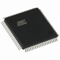
AT89C5132-RORUL Atmel, AT89C5132-RORUL Datasheet - Page 88

AT89C5132-RORUL
Manufacturer Part Number
AT89C5132-RORUL
Description
MCU 8051 FLASH USB 80TQFP
Manufacturer
Atmel
Series
AT89C513xr
Specifications of AT89C5132-RORUL
Core Processor
C52X2
Core Size
8-Bit
Speed
20MHz
Connectivity
IDE/ATAPI, I²C, MMC, PCM, SPI, UART/USART, USB
Peripherals
I²S, POR, WDT
Number Of I /o
44
Program Memory Size
64KB (64K x 8)
Program Memory Type
FLASH
Eeprom Size
4K x 8
Ram Size
2.25K x 8
Voltage - Supply (vcc/vdd)
2.7 V ~ 3.3 V
Data Converters
A/D 2x10b
Oscillator Type
Internal
Operating Temperature
-40°C ~ 85°C
Package / Case
80-TQFP, 80-VQFP
Lead Free Status / RoHS Status
Lead free / RoHS Compliant
Available stocks
Company
Part Number
Manufacturer
Quantity
Price
- Current page: 88 of 182
- Download datasheet (2Mb)
Figure 16-9. MMC Controller Block Diagram
16.4
Figure 16-10. MMC Clock Generator and Symbol
Figure 16-11. Configuration Flow
16.5
88
Clock Generator
Command Line Controller
AT89C5132
CLOCK
Internal
OSC
Bus
CLOCK
OSC
MMCON2.7
MMCEN
The MMC clock is generated by division of the oscillator clock (F
troller block as detailed in Section "Oscillator", page 12. The division factor is given by MMCD7:0
Bits in MMCLK register. Figure 16-10 shows the MMC clock generator and its output clock cal-
culation formula.
As soon as MMCEN bit in MMCON2 is set, the MMC controller receives its system clock. The
MMC command and data clock is generated on MCLK output and sent to the command line and
data line controllers. Figure 16-11 shows the MMC controller configuration flow.
As exposed in Section “Clock Control”, MMCD7:0 Bits can be used to dynamically increase or
reduce the MMC clock.
As shown in Figure 16-12, the command line controller is divided in two channels: the command
transmitter channel that handles the command transmission to the card through the MCMD line
and the command receiver channel that handles the response reception from the card through
the MCMD line. These channels are detailed in the following sections.
Generator
Clock
8
MMCD7:0
MMCLK
Configure MMC Clock
MMC Controller
Configuration
MMCLK = XXh
MMCEN = 1
FLOWC = 0
Command Line
Controller
Controller
Data Line
Controller Clock
MMC Clock
Controller
Interrupt
MMCclk
OSC
MMC Clock Symbol
) issued from the Clock Con-
CLOCK
MMC
=
---------------------------- -
MMCD
MMC
Interrupt
Request
OSCclk
MCLK
MCMD
MDAT
4173E–USB–09/07
+
1
Related parts for AT89C5132-RORUL
Image
Part Number
Description
Manufacturer
Datasheet
Request
R

Part Number:
Description:
Manufacturer:
Atmel Corporation
Datasheet:

Part Number:
Description:
IC 8051 MCU FLASH 64K USB 80TQFP
Manufacturer:
Atmel
Datasheet:

Part Number:
Description:
DEV KIT FOR AVR/AVR32
Manufacturer:
Atmel
Datasheet:

Part Number:
Description:
INTERVAL AND WIPE/WASH WIPER CONTROL IC WITH DELAY
Manufacturer:
ATMEL Corporation
Datasheet:

Part Number:
Description:
Low-Voltage Voice-Switched IC for Hands-Free Operation
Manufacturer:
ATMEL Corporation
Datasheet:

Part Number:
Description:
MONOLITHIC INTEGRATED FEATUREPHONE CIRCUIT
Manufacturer:
ATMEL Corporation
Datasheet:

Part Number:
Description:
AM-FM Receiver IC U4255BM-M
Manufacturer:
ATMEL Corporation
Datasheet:

Part Number:
Description:
Monolithic Integrated Feature Phone Circuit
Manufacturer:
ATMEL Corporation
Datasheet:

Part Number:
Description:
Multistandard Video-IF and Quasi Parallel Sound Processing
Manufacturer:
ATMEL Corporation
Datasheet:

Part Number:
Description:
High-performance EE PLD
Manufacturer:
ATMEL Corporation
Datasheet:

Part Number:
Description:
8-bit Flash Microcontroller
Manufacturer:
ATMEL Corporation
Datasheet:


