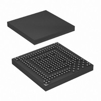
AT91SAM9G20B-CFU Atmel, AT91SAM9G20B-CFU Datasheet - Page 9

AT91SAM9G20B-CFU
Manufacturer Part Number
AT91SAM9G20B-CFU
Description
IC MCU ARM9 247-LFBGA
Manufacturer
Atmel
Series
AT91SAMr
Datasheet
1.AT91SAM9G20B-CU.pdf
(42 pages)
Specifications of AT91SAM9G20B-CFU
Core Processor
ARM9
Core Size
16/32-Bit
Speed
400MHz
Connectivity
EBI/EMI, Ethernet, I²C, IrDA, ISI, MMC, SPI, SSC, UART/USART, USB
Peripherals
DMA, POR, PWM, WDT
Number Of I /o
96
Program Memory Size
64KB (64K x 8)
Program Memory Type
ROM
Ram Size
96K x 8
Voltage - Supply (vcc/vdd)
0.9 V ~ 1.1 V
Data Converters
A/D 4x10b
Oscillator Type
Internal
Operating Temperature
-40°C ~ 85°C
Package / Case
247-TFBGA
Processor Series
AT91SAMx
Core
ARM926EJ-S
Data Bus Width
32 bit
Data Ram Size
16 KB
Interface Type
SPI, TWI, UART
Maximum Clock Frequency
400 MHz
Number Of Programmable I/os
96
Operating Supply Voltage
3.3 V
Maximum Operating Temperature
+ 85 C
Mounting Style
SMD/SMT
3rd Party Development Tools
JTRACE-ARM-2M, MDK-ARM, RL-ARM, ULINK2
Development Tools By Supplier
AT91SAM-ICE, AT91-ISP, AT91SAM9G20-EK
Minimum Operating Temperature
- 40 C
Lead Free Status / RoHS Status
Lead free / RoHS Compliant
Eeprom Size
-
Lead Free Status / Rohs Status
Details
Available stocks
Company
Part Number
Manufacturer
Quantity
Price
Table 3-1.
Note:
4. Package and Pinout
4.1
6384DS–ATARM–13-Jan-10
Signal Name
ISI_D0-ISI_D11
ISI_MCK
ISI_HSYNC
ISI_VSYNC
ISI_PCK
AD0-AD3
ADVREF
ADTRG
No PLLRCA line present on the AT91SAM9G20.
217-ball LFBGA Package Outline
Signal Description List (Continued)
Figure 4-1
A detailed mechanical description is given in the section “AT91SAM9G20 Mechanical Charac-
teristics” of the product datasheet.
Figure 4-1.
• The AT91SAM9G20 is available in a 217-ball, 15 x 15 mm, LFBGA package (0.8 mm pitch)
• The AT91SAM9G20 is available in a 247-ball, 10 x 10 x 1.1 mm, TFBGA Green package, ,
(Figure
(0.5 mm pitch)
Function
Image Sensor Reference Clock
Image Sensor Horizontal Synchro
Image Sensor Vertical Synchro
Image Sensor Data clock
Analog Inputs
Analog Positive Reference
ADC Trigger
Image Sensor Data
shows the orientation of the 217-ball LFBGA package.
4-1).
217-ball LFBGA Package (Top View)
(Figure
Analog to Digital Converter
Image Sensor Interface
Ball A1
4-2).
17
16
15
14
13
12
11
10
9
8
7
6
5
4
3
2
1
A B C D E F G H J K L M N P R T U
Analog
Analog
Output
Type
Input
Input
Input
Input
Input
AT91SAM9G20 Summary
Active
Level
Comments
Digital pulled-up inputs at reset
9


