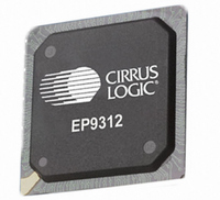
EP9312-IB Cirrus Logic Inc, EP9312-IB Datasheet - Page 135

EP9312-IB
Manufacturer Part Number
EP9312-IB
Description
IC ARM920T MCU 200MHZ 352-PBGA
Manufacturer
Cirrus Logic Inc
Series
EP9r
Datasheets
1.EP9307-CRZ.pdf
(824 pages)
2.EP9312-IBZ.pdf
(4 pages)
3.EP9312-CB.pdf
(62 pages)
4.EP9312-CB.pdf
(17 pages)
Specifications of EP9312-IB
Core Processor
ARM9
Core Size
16/32-Bit
Speed
200MHz
Connectivity
EBI/EMI, EIDE, Ethernet, I²C, IrDA, Keypad/Touchscreen, SPI, UART/USART, USB
Peripherals
AC'97, DMA, I²:S, LCD, LED, MaverickKey, POR, PWM, WDT
Number Of I /o
16
Program Memory Type
ROMless
Ram Size
32K x 8
Voltage - Supply (vcc/vdd)
1.65 V ~ 3.6 V
Data Converters
A/D 8x12b
Oscillator Type
External
Operating Temperature
-40°C ~ 85°C
Package / Case
352-BGA
Processor Series
EP93xx
Core
ARM920T
Data Bus Width
32 bit
3rd Party Development Tools
MDK-ARM, RL-ARM, ULINK2
Lead Free Status / RoHS Status
Contains lead / RoHS non-compliant
Eeprom Size
-
Program Memory Size
-
Lead Free Status / Rohs Status
No
Other names
598-1259
Available stocks
Company
Part Number
Manufacturer
Quantity
Price
Company:
Part Number:
EP9312-IBZ
Manufacturer:
CIRRUS
Quantity:
30
Company:
Part Number:
EP9312-IBZ
Manufacturer:
HITTITE
Quantity:
1 200
- EP9307-CRZ PDF datasheet
- EP9312-IBZ PDF datasheet #2
- EP9312-CB PDF datasheet #3
- EP9312-CB PDF datasheet #4
- Current page: 135 of 824
- Download datasheet (13Mb)
DS785UM1
5.1.5.3 Steps for Clock Configuration
5.1.6 Power Management
5.1.6.1 Clock Gatings
The boot ROM must contain code that performs the following steps for a 14.7456 MHz
crystal. The actual register values should be taken from the register descriptions for the
desired clock setup.
The device follows a power-saving design plan. Power management is done by either
altering the PLLs or the clock system frequency or by shutting off clocks to unused blocks.
Also, there are several system power states to which the device can transition in order to
save power. Care must be taken to ensure the clock system is not put into a non-operational
state and that clock system dependencies are observed.
The list of peripherals with PCLK gating is shown
in this user’s guide to find detailed information about clock gatings for a specific peripheral.
1. After power up, the reset state of all clock control registers (all bits zero) will ensure that
2. Configure PLL1 to multiply by the desired value, set HCLK and FCLK rates, and power it
3. Configure PLL2 to multiply by the desired value. To do this, write the proper value to
4. Wait for PLL2 to stabilize (at least 1 ms)
5. Program all other clock dividers to the desired values and enable them. The clocks won’t
6. All peripherals are now running from divided PLL outputs. Once the clocks have been
FCLK and HCLK are running at the crystal oscillator frequency of 14.7456 MHz.
up. To do this: write the proper value (taken from the register table) to
immediately followed by 5 NOP instructions to flush the ARM Core’s instruction pipeline.
The ARM Core will go into Standby mode while PLL1 stabilizes, then it returns to normal
operation at the new clock rates.
"ClkSet2".
actually begin running until the clock sources which feed them are enabled. Write the
desired values to these registers:
configured, the frequency of any peripheral clock can be changed on-the-fly. To do this,
perform a write to the clock register with the new divisor value and then set the
appropriate enable bit. This ensures a problem-free change of the clock.
•
•
•
•
“VidClkDiv” on page 5-29
“MIRClkDiv” on page 5-30
“I2SClkDiv” on page 5-31
“KeyTchClkDiv” on page 5-32
Copyright 2007 Cirrus Logic
Table
5-4. Refer to the appropriate chapter
EP93xx User’s Guide
"ClkSet1"
System Controller
5-9
5
Related parts for EP9312-IB
Image
Part Number
Description
Manufacturer
Datasheet
Request
R

Part Number:
Description:
IC ARM920T MCU 200MHZ 352-PBGA
Manufacturer:
Cirrus Logic Inc
Datasheet:

Part Number:
Description:
IC ARM9 SOC UNIVERSAL 352PBGA
Manufacturer:
Cirrus Logic Inc
Datasheet:

Part Number:
Description:
System-on-Chip Processor
Manufacturer:
Cirrus Logic Inc
Datasheet:

Part Number:
Description:
IC ARM920T MCU 200MHZ 352-PBGA
Manufacturer:
Cirrus Logic Inc
Datasheet:

Part Number:
Description:
IC ARM920T MCU 200MHZ 352-PBGA
Manufacturer:
Cirrus Logic Inc
Datasheet:

Part Number:
Description:
IC ARM920T MCU 166MHZ 208-LQFP
Manufacturer:
Cirrus Logic Inc
Datasheet:

Part Number:
Description:
IC ARM920T MCU 166MHZ 208-LQFP
Manufacturer:
Cirrus Logic Inc
Datasheet:

Part Number:
Description:
Development Kit
Manufacturer:
Cirrus Logic Inc
Datasheet:

Part Number:
Description:
Development Kit
Manufacturer:
Cirrus Logic Inc
Datasheet:

Part Number:
Description:
High-efficiency PFC + Fluorescent Lamp Driver Reference Design
Manufacturer:
Cirrus Logic Inc
Datasheet:

Part Number:
Description:
Development Kit
Manufacturer:
Cirrus Logic Inc
Datasheet:

Part Number:
Description:
Development Kit
Manufacturer:
Cirrus Logic Inc
Datasheet:

Part Number:
Description:
Ref Bd For Speakerbar MSA & DSP Products
Manufacturer:
Cirrus Logic Inc


