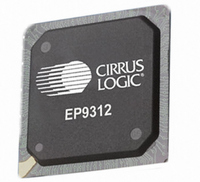
EP9312-IB Cirrus Logic Inc, EP9312-IB Datasheet - Page 696

EP9312-IB
Manufacturer Part Number
EP9312-IB
Description
IC ARM920T MCU 200MHZ 352-PBGA
Manufacturer
Cirrus Logic Inc
Series
EP9r
Datasheets
1.EP9307-CRZ.pdf
(824 pages)
2.EP9312-IBZ.pdf
(4 pages)
3.EP9312-CB.pdf
(62 pages)
4.EP9312-CB.pdf
(17 pages)
Specifications of EP9312-IB
Core Processor
ARM9
Core Size
16/32-Bit
Speed
200MHz
Connectivity
EBI/EMI, EIDE, Ethernet, I²C, IrDA, Keypad/Touchscreen, SPI, UART/USART, USB
Peripherals
AC'97, DMA, I²:S, LCD, LED, MaverickKey, POR, PWM, WDT
Number Of I /o
16
Program Memory Type
ROMless
Ram Size
32K x 8
Voltage - Supply (vcc/vdd)
1.65 V ~ 3.6 V
Data Converters
A/D 8x12b
Oscillator Type
External
Operating Temperature
-40°C ~ 85°C
Package / Case
352-BGA
Processor Series
EP93xx
Core
ARM920T
Data Bus Width
32 bit
3rd Party Development Tools
MDK-ARM, RL-ARM, ULINK2
Lead Free Status / RoHS Status
Contains lead / RoHS non-compliant
Eeprom Size
-
Program Memory Size
-
Lead Free Status / Rohs Status
No
Other names
598-1259
Available stocks
Company
Part Number
Manufacturer
Quantity
Price
Company:
Part Number:
EP9312-IBZ
Manufacturer:
CIRRUS
Quantity:
30
Company:
Part Number:
EP9312-IBZ
Manufacturer:
HITTITE
Quantity:
1 200
- EP9307-CRZ PDF datasheet
- EP9312-IBZ PDF datasheet #2
- EP9312-CB PDF datasheet #3
- EP9312-CB PDF datasheet #4
- Current page: 696 of 824
- Download datasheet (13Mb)
22
22-8
AC’97 Controller
EP93xx User’s Guide
Definition:
Bit Descriptions:
Receive Control Registers. The AC97RXCR registers are read/write registers
that are 32 bits. The data contained within the register controls the data slots
that are contained within the receive FIFO. The data contained within the
RSIZE bits controls the number of zeros that are to be appended to data to
make it 20 bits.
Should two channels be enabled for the same data slot, then data is taken
from, or given to, the lower channel number.
The data from the receive channel is stored in the lowest slot first. If for
example the receive FIFO is setup to store slots 3 and 4 then the first data
word out of the FIFO will be slot 3 followed by slot 4.
RSVD:
TOC:
FDIS:
CM:
Copyright 2007 Cirrus Logic
Reserved. Unknown During Read.
Time out count value. The FIFOs have the capability of
generating a timeout interrupt when the receive FIFO is
not empty and no further data is received for a period of
time. This time period is specified by the value written
here. The value is the number of frames that must occur
without any data being received (a count of the SYNC
signal). A write of “0” to this value disables the counter,
and no timeout interrupt is generated. On reset the value
is “0”. The maximum count of 4096 will allow the timeout
period to be set to 85 msec.
FIFO Disable
0 - The FIFO buffers are Enabled (FIFO mode).
1 - The FIFO is disabled (character mode). That is, the
FIFO becomes 1-byte-deep holding registers.
Compact mode enable. If the RSIZE value is either “00” or
“11” (setting the data word size to 12- or 16-bits) then the
CM bit determines whether the two data words are
compacted into one 32-bit word, or each is sent in a
separate word. If the RSIZE value is either “01” or “10”
(setting the data word size to 18- or 20-bits) then the CM
bit has no effect. See
0 - The data is justified into separate 32 bit words
1 - The two data words are compacted into one 32-bit
word for reading by the CPU.
Table
22-3.
DS785UM1
Related parts for EP9312-IB
Image
Part Number
Description
Manufacturer
Datasheet
Request
R

Part Number:
Description:
IC ARM920T MCU 200MHZ 352-PBGA
Manufacturer:
Cirrus Logic Inc
Datasheet:

Part Number:
Description:
IC ARM9 SOC UNIVERSAL 352PBGA
Manufacturer:
Cirrus Logic Inc
Datasheet:

Part Number:
Description:
System-on-Chip Processor
Manufacturer:
Cirrus Logic Inc
Datasheet:

Part Number:
Description:
IC ARM920T MCU 200MHZ 352-PBGA
Manufacturer:
Cirrus Logic Inc
Datasheet:

Part Number:
Description:
IC ARM920T MCU 200MHZ 352-PBGA
Manufacturer:
Cirrus Logic Inc
Datasheet:

Part Number:
Description:
IC ARM920T MCU 166MHZ 208-LQFP
Manufacturer:
Cirrus Logic Inc
Datasheet:

Part Number:
Description:
IC ARM920T MCU 166MHZ 208-LQFP
Manufacturer:
Cirrus Logic Inc
Datasheet:

Part Number:
Description:
Development Kit
Manufacturer:
Cirrus Logic Inc
Datasheet:

Part Number:
Description:
Development Kit
Manufacturer:
Cirrus Logic Inc
Datasheet:

Part Number:
Description:
High-efficiency PFC + Fluorescent Lamp Driver Reference Design
Manufacturer:
Cirrus Logic Inc
Datasheet:

Part Number:
Description:
Development Kit
Manufacturer:
Cirrus Logic Inc
Datasheet:

Part Number:
Description:
Development Kit
Manufacturer:
Cirrus Logic Inc
Datasheet:

Part Number:
Description:
Ref Bd For Speakerbar MSA & DSP Products
Manufacturer:
Cirrus Logic Inc


