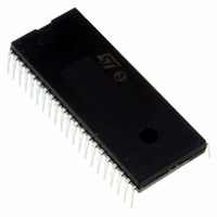
ST72F324J4B6 STMicroelectronics, ST72F324J4B6 Datasheet - Page 145

ST72F324J4B6
Manufacturer Part Number
ST72F324J4B6
Description
IC MCU 8BIT 16K FLASH 42-PDIP
Manufacturer
STMicroelectronics
Series
ST7r
Datasheet
1.ST72F324J2T6.pdf
(164 pages)
Specifications of ST72F324J4B6
Core Processor
ST7
Core Size
8-Bit
Speed
8MHz
Connectivity
SCI, SPI
Peripherals
LVD, POR, PWM, WDT
Number Of I /o
32
Program Memory Size
16KB (16K x 8)
Program Memory Type
FLASH
Ram Size
512 x 8
Voltage - Supply (vcc/vdd)
3.8 V ~ 5.5 V
Data Converters
A/D 12x10b
Oscillator Type
Internal
Operating Temperature
-40°C ~ 85°C
Package / Case
42-DIP (0.600", 15.24mm)
Processor Series
ST72F3x
Core
ST7
Data Bus Width
8 bit
Data Ram Size
512 B
Interface Type
SCI, SPI
Maximum Clock Frequency
8 MHz
Number Of Programmable I/os
32
Number Of Timers
4 bit
Operating Supply Voltage
3.8 V to 5.5 V
Maximum Operating Temperature
+ 85 C
Mounting Style
Through Hole
Development Tools By Supplier
ST7F521-IND/USB, ST7232X-EVAL, ST7MDT20-DVP3, ST7MDT20J-EMU3, STX-RLINK
Minimum Operating Temperature
- 40 C
On-chip Adc
10 bit
For Use With
497-6421 - BOARD EVAL DGTL BATT CHGR DESIGN
Lead Free Status / RoHS Status
Lead free / RoHS Compliant
Eeprom Size
-
Lead Free Status / Rohs Status
Details
Available stocks
Company
Part Number
Manufacturer
Quantity
Price
Part Number:
ST72F324J4B6
Manufacturer:
ST
Quantity:
20 000
10-BIT ADC CHARACTERISTICS (Cont’d)
12.13.3 ADC Accuracy
Conditions: V
Notes:
1. ADC Accuracy vs. Negative Injection Current: Injecting negative current may reduce the accuracy of the conversion
being performed on another analog input.
Any positive injection current within the limits specified for I
accuracy.
2. Data based on characterization results, monitored in production to guarantee 99.73% within ± max value from -40°C
to 125°C (± 3σ distribution limits).
Figure 87. ADC Accuracy Characteristics
Symbol
1023
1022
1021
|E
|E
|E
|E
|E
7
6
5
4
3
2
1
O
G
D
T
L
0
V
|
|
|
|
|
SSA
Digital Result ADCDR
1LSB
Total unadjusted error
Offset error
Gain Error
Differential linearity error
1)
Integral linearity error
1
E
O
IDEAL
DD
2
Parameter
=5V
1)
3
=
1)
V
--------------------------------------------
1)
AREF
4
1024
5
–
1 LSB
1)
V
1)
SSA
E
6
T
IDEAL
CPU in run mode @ f
CPU in run mode @ f
E
7
L
(2)
E
D
1021 1022 1023 1024
(3)
Conditions
INJ(PIN)
(1)
ADC
ADC
E
2 MHz.
2 MHz.
G
V
AREF
and ΣI
(1) Example of an actual transfer curve
(2) The ideal transfer curve
(3) End point correlation line
E
between the actual and the ideal transfer curves.
E
transition and the first ideal one.
E
transition and the last actual one.
E
between actual steps and the ideal one.
E
between any actual transition and the end point
correlation line.
INJ(PIN)
T
O
G
D
L
=Total Unadjusted Error: maximum deviation
=Integral Linearity Error: maximum deviation
=Offset Error: deviation between the first actual
=Gain Error: deviation between the last ideal
=Differential Linearity Error: maximum deviation
V
in
(LSB
in
Section 12.9
IDEAL
ST72324Jx ST72324Kx
)
Flash Devices
Typ
0.5
1.5
1.5
4
3
does not affect the ADC
Max
4.5
4.5
4.5
6
5
2)
145/164
Unit
LSB
1


