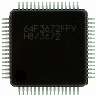
HD64F3672FPV Renesas Electronics America, HD64F3672FPV Datasheet - Page 266

HD64F3672FPV
Manufacturer Part Number
HD64F3672FPV
Description
IC H8/3672 MCU FLASH 64LQFP
Manufacturer
Renesas Electronics America
Series
H8® H8/300H Tinyr
Datasheets
1.DF36912GFHV.pdf
(277 pages)
2.DF36012GFYV.pdf
(1021 pages)
3.HD64F3672FXV.pdf
(334 pages)
Specifications of HD64F3672FPV
Core Processor
H8/300H
Core Size
16-Bit
Speed
16MHz
Connectivity
SCI
Peripherals
PWM, WDT
Number Of I /o
26
Program Memory Size
16KB (16K x 8)
Program Memory Type
FLASH
Ram Size
2K x 8
Voltage - Supply (vcc/vdd)
3 V ~ 5.5 V
Data Converters
A/D 4x10b
Oscillator Type
Internal
Operating Temperature
-20°C ~ 75°C
Package / Case
64-LQFP
For Use With
R0K436079S000BE - KIT DEV FOR H8/36079 W/COMPILER
Lead Free Status / RoHS Status
Lead free / RoHS Compliant
Eeprom Size
-
Available stocks
Company
Part Number
Manufacturer
Quantity
Price
Company:
Part Number:
HD64F3672FPV
Manufacturer:
MICROCHIP
Quantity:
1 000
Company:
Part Number:
HD64F3672FPV
Manufacturer:
Renesas Electronics America
Quantity:
135
Company:
Part Number:
HD64F3672FPV
Manufacturer:
Renesas Electronics America
Quantity:
10 000
Part Number:
HD64F3672FPV
Manufacturer:
RENESAS/瑞萨
Quantity:
20 000
- Current page: 266 of 277
- Download datasheet (2Mb)
Section 3 Processing States
3.4
This is a state in which the bus has been released in response to a bus request from a bus master
other than the CPU. While the bus is released, the CPU halts except for internal operations. For
further details, refer to the relevant microcontroller hardware manual.
3.5
When the RES input goes low all current processing stops and the CPU enters the reset state. The I
bit in the condition-code register is set to 1 by a reset. All interrupts are masked in the reset state.
Reset exception handling starts when the RES signal changes from low to high.
3.6
In the power-down state the CPU stops operating to conserve power. There are three modes: sleep
mode, software standby mode, and hardware standby mode. For details, refer to the relevant
microcontroller hardware manual.
3.6.1
A transition to sleep mode is made if the SLEEP instruction is executed while the software
standby bit (SSBY) is cleared to 0.
CPU operations stop immediately after execution of the SLEEP instruction. The contents of CPU
registers are retained.
3.6.2
A transition to software standby mode is made if the SLEEP instruction is executed while the
SSBY bit is set to 1.
The CPU and clock halt and all on-chip supporting modules stop operating. The on-chip
supporting modules are reset, but as long as a specified voltage is supplied the contents of CPU
registers and on-chip RAM are retained. The I/O ports also remain in their existing states.
Rev. 3.00 Dec 13, 2004 page 250 of 258
REJ09B0213-0300
For further details, refer to the relevant microcontroller hardware manual.
Bus-Released State
Reset State
Power-Down State
Sleep Mode
Software Standby Mode
Related parts for HD64F3672FPV
Image
Part Number
Description
Manufacturer
Datasheet
Request
R

Part Number:
Description:
KIT STARTER FOR M16C/29
Manufacturer:
Renesas Electronics America
Datasheet:

Part Number:
Description:
KIT STARTER FOR R8C/2D
Manufacturer:
Renesas Electronics America
Datasheet:

Part Number:
Description:
R0K33062P STARTER KIT
Manufacturer:
Renesas Electronics America
Datasheet:

Part Number:
Description:
KIT STARTER FOR R8C/23 E8A
Manufacturer:
Renesas Electronics America
Datasheet:

Part Number:
Description:
KIT STARTER FOR R8C/25
Manufacturer:
Renesas Electronics America
Datasheet:

Part Number:
Description:
KIT STARTER H8S2456 SHARPE DSPLY
Manufacturer:
Renesas Electronics America
Datasheet:

Part Number:
Description:
KIT STARTER FOR R8C38C
Manufacturer:
Renesas Electronics America
Datasheet:

Part Number:
Description:
KIT STARTER FOR R8C35C
Manufacturer:
Renesas Electronics America
Datasheet:

Part Number:
Description:
KIT STARTER FOR R8CL3AC+LCD APPS
Manufacturer:
Renesas Electronics America
Datasheet:

Part Number:
Description:
KIT STARTER FOR RX610
Manufacturer:
Renesas Electronics America
Datasheet:

Part Number:
Description:
KIT STARTER FOR R32C/118
Manufacturer:
Renesas Electronics America
Datasheet:

Part Number:
Description:
KIT DEV RSK-R8C/26-29
Manufacturer:
Renesas Electronics America
Datasheet:

Part Number:
Description:
KIT STARTER FOR SH7124
Manufacturer:
Renesas Electronics America
Datasheet:

Part Number:
Description:
KIT STARTER FOR H8SX/1622
Manufacturer:
Renesas Electronics America
Datasheet:


