HD64F3642AH Renesas Electronics America, HD64F3642AH Datasheet - Page 342
HD64F3642AH
Manufacturer Part Number
HD64F3642AH
Description
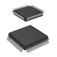
IC H8 MCU FLASH 16K 64QFP
Manufacturer
Renesas Electronics America
Series
H8® H8/300Lr
Datasheet
1.HD64F3644HV.pdf
(551 pages)
Specifications of HD64F3642AH
Core Processor
H8/300L
Core Size
8-Bit
Speed
8MHz
Connectivity
SCI
Peripherals
PWM, WDT
Number Of I /o
53
Program Memory Size
16KB (16K x 8)
Program Memory Type
FLASH
Ram Size
1K x 8
Voltage - Supply (vcc/vdd)
2.7 V ~ 5.5 V
Data Converters
A/D 8x8b
Oscillator Type
Internal
Operating Temperature
-20°C ~ 75°C
Package / Case
64-QFP
Lead Free Status / RoHS Status
Contains lead / RoHS non-compliant
Eeprom Size
-
Available stocks
Company
Part Number
Manufacturer
Quantity
Price
Company:

Part Number:
HD64F3642AH
Manufacturer:
HITACHI
Quantity:
12
Company:
Part Number:
HD64F3642AH
Manufacturer:
HITACHI
Quantity:
648
Company:
Part Number:
HD64F3642AH
Manufacturer:
Renesas Electronics America
Quantity:
10 000
Company:
Part Number:
HD64F3642AHV
Manufacturer:
RENESAS
Quantity:
1 000
Company:
Part Number:
HD64F3642AHV
Manufacturer:
Renesas Electronics America
Quantity:
10 000
Company:
Part Number:
HD64F3642AHV H8/3642A
Manufacturer:
RENESAS
Quantity:
190


Section 10 Serial Communication Interface
SCI3 operates as follows when receiving data.
SCI3 monitors the communication line, and when it detects a 0 start bit, performs internal
synchronization and begins reception. Reception is carried out in accordance with the relevant data
transfer format in table 10.14. The received data is first placed in RSR in LSB-to-MSB order, and
then the parity bit and stop bit(s) are received. SCI3 then carries out the following checks.
Rev. 6.00 Sep 12, 2006 page 320 of 526
REJ09B0326-0600
4
Parity check
SCI3 checks that the number of 1 bits in the receive data conforms to the parity (odd or even)
set in bit PM in the serial mode register (SMR).
Stop bit check
SCI3 checks that the stop bit is 1. If two stop bits are used, only the first is checked.
Status check
SCI3 checks that bit RDRF is set to 1, indicating that the receive data can be transferred from
RSR to RDR.
Clear bits OER, PER,
Figure 10.13 Example of Data Reception Flowchart (Asynchronous Mode) (cont)
FER to 0 in SSR
error processing
error processing
End of receive
Start receive
No
No
No
OER = 1?
PER = 1?
FER = 1?
Yes
Yes
Yes
Parity error
processing
Framing error
Overrun error
processing
processing
Break?
No
Yes
(A)
4.
If a receive error has
occurred, read bits OER,
PER, and FER in SSR to
identify the error, and after
carrying out the necessary
error processing, ensure
that bits OER, PER, and
FER are all cleared to 0.
Reception cannot be
resumed if any of these
bits is set to 1. In the case
of a framing error, a break
can be detected by reading
the value of the RXD pin.
Related parts for HD64F3642AH
Image
Part Number
Description
Manufacturer
Datasheet
Request
R

Part Number:
Description:
(HD64 Series) Hitachi Single-Chip Microcomputer
Manufacturer:
Hitachi Semiconductor
Datasheet:

Part Number:
Description:
KIT STARTER FOR M16C/29
Manufacturer:
Renesas Electronics America
Datasheet:

Part Number:
Description:
KIT STARTER FOR R8C/2D
Manufacturer:
Renesas Electronics America
Datasheet:

Part Number:
Description:
R0K33062P STARTER KIT
Manufacturer:
Renesas Electronics America
Datasheet:

Part Number:
Description:
KIT STARTER FOR R8C/23 E8A
Manufacturer:
Renesas Electronics America
Datasheet:

Part Number:
Description:
KIT STARTER FOR R8C/25
Manufacturer:
Renesas Electronics America
Datasheet:

Part Number:
Description:
KIT STARTER H8S2456 SHARPE DSPLY
Manufacturer:
Renesas Electronics America
Datasheet:

Part Number:
Description:
KIT STARTER FOR R8C38C
Manufacturer:
Renesas Electronics America
Datasheet:

Part Number:
Description:
KIT STARTER FOR R8C35C
Manufacturer:
Renesas Electronics America
Datasheet:

Part Number:
Description:
KIT STARTER FOR R8CL3AC+LCD APPS
Manufacturer:
Renesas Electronics America
Datasheet:
Part Number:
Description:
KIT STARTER FOR RX610
Manufacturer:
Renesas Electronics America
Datasheet:

Part Number:
Description:
KIT STARTER FOR R32C/118
Manufacturer:
Renesas Electronics America
Datasheet:

Part Number:
Description:
KIT DEV RSK-R8C/26-29
Manufacturer:
Renesas Electronics America
Datasheet:

Part Number:
Description:
KIT STARTER FOR SH7124
Manufacturer:
Renesas Electronics America
Datasheet:

Part Number:
Description:
KIT STARTER FOR H8SX/1622
Manufacturer:
Renesas Electronics America
Datasheet: