M30620FCAFP#D3 Renesas Electronics America, M30620FCAFP#D3 Datasheet - Page 41
M30620FCAFP#D3
Manufacturer Part Number
M30620FCAFP#D3
Description
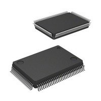
IC M16C MCU FLASH 128K 100LQFP
Manufacturer
Renesas Electronics America
Series
M16C™ M16C/60r
Specifications of M30620FCAFP#D3
Core Processor
M16C/60
Core Size
16-Bit
Speed
16MHz
Connectivity
SIO, UART/USART
Peripherals
DMA, PWM, WDT
Number Of I /o
85
Program Memory Size
128KB (128K x 8)
Program Memory Type
FLASH
Ram Size
10K x 8
Voltage - Supply (vcc/vdd)
4.2 V ~ 5.5 V
Data Converters
A/D 10x10b, D/A 2x8b
Oscillator Type
Internal
Operating Temperature
-40°C ~ 85°C
Package / Case
100-LQFP
Lead Free Status / RoHS Status
Contains lead / RoHS non-compliant
Eeprom Size
-
Available stocks
Company
Part Number
Manufacturer
Quantity
Price


Clock Generating Circuit
38
Figure 1.10.4. Clock control registers 0 and 1
Figure 1.10.4 shows the system clock control registers 0 and 1.
b7
b7
System clock control register 0 (Note 1)
System clock control register 1 (Note 1)
Note 1: Set bit 0 of the protect register (address 000A
Note 2: Changes to “1” when shiffing to stop mode and at a reset.
Note 3: When entering low power dissipation mode, main clock stops by using this bit. To stop the main clock, when the
Note 4: When inputting external clock, only clock oscillation buffer is stopped and clock input is acceptable.
Note 5: If this bit is set to “1”, X
Note 6: Set port X
Note 7: This bit changes to “1” when shifting from high-speed/medium-speed mode to stop mode and at a reset. When
Note 8: f
Note 9: When the X
Note 1: Set bit 0 of the protect register (address 000A
Note 2: This bit changes to “1” when shifting from high-speed/medium-speed mode to stop mode and at a reset. When
Note 3: Can be selected when bit 6 of the system clock control register 0 (address 0006
Note 4: If this bit is set to “1”, X
b6
b6
b5
b5
sub clock oscillation is stable, set system clock select bit (CM07) to “1” before setting this bit to “1”.
pulled up to X
Do not write to both bits at the same time. And also, set the main clock stop bit (CM05) to “0” and stabilize the
main clock oscillating before setting this bit from “1” to “0”.
shifting from low-speed/low power dissipation mode to stop mode, the value before stop mode is retained.
shifting from low-speed/low power dissipation mode to stop mode, the value before stop mode is retained.
fixed at 8.
impedance state.
C32
b4
b4
0
b3
b3
0
is not included.
b2
b2
0
C
b1
b1
0
CIN
select bit (CM04) to “1” and stabilize the sub-clock oscillating before setting this bit from “0” to “1”.
b0
b0
OUT
/X
COUT
Bit symbol
Bit symbol
(“H”) via the feedback resistor.
Reserved bit
Reserved bit
Reserved bit
Reserved bit
CM01
CM02
CM03
CM04
CM05
CM06
CM07
Do not set to
CM10
CM15
CM16
CM17
CM00
Symbol
CM0
Symbol
CM1
is used, set ports P8
OUT
OUT
turns “H”. The built-in feedback resistor remains being connected, so X
turns “H”, and the built-in feedback resistor is cut off. X
Port X
Main clock division select
bit 0 (Note 7)
Main clock division
select bit 1 (Note 3)
Clock output function
select bit
(Valid only in single-chip
mode)
WAIT peripheral function
clock stop bit
X
select bit (Note 2)
Main clock (X
stop bit (Note 3, 4, 5)
System clock select bit
(Note 6)
All clock stop control bit
(Note4)
X
select bit (Note 2)
IN
CIN
-X
“1”
-X
OUT
C
COUT
when using low-speed or low power dissipation mode.
select bit
Bit name
Bit name
drive capacity
drive capacity
Address
Address
IN
0006
0007
6
-X
and P8
16
16
OUT
) to “1” before writing to this register.
) to “1” before writing to this register.
16
16
)
7
as the input ports without pull-up.
When reset
When reset
0 : Do not stop peripheral function clock in wait mode
1 : Stop peripheral function clock in wait mode (Note 8)
0 : LOW
1 : HIGH
0 : CM16 and CM17 valid
1 : Division by 8 mode
b7 b6
b1 b0
0 0 : I/O port P5
0 1 : f
1 0 : f
1 1 : f
0 : I/O port
1 : X
0 : On
1 : Off
0 : X
1 : X
0 : Clock on
1 : All clocks off (stop mode)
0 0 : No division mode
0 1 : Division by 2 mode
1 0 : Division by 4 mode
1 1 : Division by 16 mode
Always set to
Always set to
Always set to
Always set to
0 : LOW
1 : HIGH
48
20
CIN
IN
CIN
16
C
8
32
16
, X
output
output
-X
, X
output
OUT
COUT
COUT
“0”
“0”
“0”
“0”
generation (Note 9)
7
SINGLE-CHIP 16-BIT CMOS MICROCOMPUTER
Function
Function
16
) is “0”. If “1”, division mode is
CIN
and X
COUT
M16C / 62A Group
turn high-
Mitsubishi microcomputers
IN
turns
R
R
W
W
Related parts for M30620FCAFP#D3
Image
Part Number
Description
Manufacturer
Datasheet
Request
R

Part Number:
Description:
KIT STARTER FOR M16C/29
Manufacturer:
Renesas Electronics America
Datasheet:

Part Number:
Description:
KIT STARTER FOR R8C/2D
Manufacturer:
Renesas Electronics America
Datasheet:

Part Number:
Description:
R0K33062P STARTER KIT
Manufacturer:
Renesas Electronics America
Datasheet:

Part Number:
Description:
KIT STARTER FOR R8C/23 E8A
Manufacturer:
Renesas Electronics America
Datasheet:

Part Number:
Description:
KIT STARTER FOR R8C/25
Manufacturer:
Renesas Electronics America
Datasheet:

Part Number:
Description:
KIT STARTER H8S2456 SHARPE DSPLY
Manufacturer:
Renesas Electronics America
Datasheet:

Part Number:
Description:
KIT STARTER FOR R8C38C
Manufacturer:
Renesas Electronics America
Datasheet:

Part Number:
Description:
KIT STARTER FOR R8C35C
Manufacturer:
Renesas Electronics America
Datasheet:

Part Number:
Description:
KIT STARTER FOR R8CL3AC+LCD APPS
Manufacturer:
Renesas Electronics America
Datasheet:
Part Number:
Description:
KIT STARTER FOR RX610
Manufacturer:
Renesas Electronics America
Datasheet:

Part Number:
Description:
KIT STARTER FOR R32C/118
Manufacturer:
Renesas Electronics America
Datasheet:

Part Number:
Description:
KIT DEV RSK-R8C/26-29
Manufacturer:
Renesas Electronics America
Datasheet:

Part Number:
Description:
KIT STARTER FOR SH7124
Manufacturer:
Renesas Electronics America
Datasheet:

Part Number:
Description:
KIT STARTER FOR H8SX/1622
Manufacturer:
Renesas Electronics America
Datasheet:

Part Number:
Description:
KIT DEV FOR SH7203
Manufacturer:
Renesas Electronics America
Datasheet: