MAXQ622G-0000+ Maxim Integrated Products, MAXQ622G-0000+ Datasheet - Page 25

MAXQ622G-0000+
Manufacturer Part Number
MAXQ622G-0000+
Description
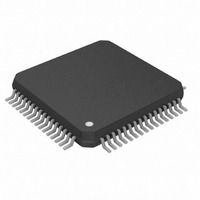
IC MCU 16BIT 64K IR MOD 64LQFP
Manufacturer
Maxim Integrated Products
Series
MAXQ™r
Datasheet
1.MAXQ622G-0000.pdf
(31 pages)
Specifications of MAXQ622G-0000+
Core Processor
RISC
Core Size
16-Bit
Speed
12MHz
Connectivity
I²C, SPI, UART/USART, USB
Peripherals
Brown-out Detect/Reset, Infrared, Power-Fail, POR, WDT
Number Of I /o
44
Program Memory Size
128KB (128K x 8)
Program Memory Type
FLASH
Ram Size
6K x 8
Voltage - Supply (vcc/vdd)
1.7 V ~ 3.6 V
Oscillator Type
Internal
Operating Temperature
0°C ~ 70°C
Package / Case
64-LQFP
Processor Series
MAXQ622
Core
RISC
Data Bus Width
16 bit
Data Ram Size
6 KB
Interface Type
I2C, SPI, USART
Maximum Clock Frequency
12 MHz
Number Of Programmable I/os
44
Number Of Timers
2
Operating Supply Voltage
1.7 V to 3.6 V
Maximum Operating Temperature
+ 70 C
Mounting Style
SMD/SMT
Development Tools By Supplier
MAXQUSBJTAG-KIT MAXQ622-KIT
Minimum Operating Temperature
0 C
For Use With
MAXQ622-KIT# - EVALUATION KIT FOR MAXQ622
Lead Free Status / RoHS Status
Lead free / RoHS Compliant
Eeprom Size
-
Data Converters
-
Lead Free Status / Rohs Status
Details
Table 4. Power-Fail Warning Level Selection
Figure 5. Power-Fail Detection During Normal Operation
mode to minimize power consumption. This feature is
enabled using the power-fail monitor disable (PFD) bit
in the PWCN register. The reset default state for the PFD
bit is 1, which disables the power-fail monitor function
during stop mode. If power-fail monitoring is disabled
(PFD = 1) during stop mode, the circuitry responsible
for generating a power-fail warning or reset is shut down
and neither condition is detected. Thus, the V
condition does not invoke a reset state. However, in the
event that V
erated. The power-fail monitor is enabled prior to stop
mode exit and before code execution begins. If a power-
fail warning condition (V
the power-fail interrupt flag is set on stop mode exit. If a
power-fail reset condition is detected (V
CPU goes into reset.
PWCN.PFWARNCN[1:0]
INTERNAL RESET
(ACTIVE HIGH)
V
V
V
DD
PFW
POR
RST
00
01
10
11
falls below the POR level, a POR is gen-
______________________________________________________________________________________
V
DD
A
B
DD
C
< V
PFW
Infrared Module and Optional USB
PFW THRESHOLD
t < t
) is then detected,
D
PFW
2.55
2.75
DD
1.8
1.9
(V)
< V
DD
RST
16-Bit Microcontrollers with
t ≥ t
< V
), the
PFW
RST
E
The power-fail monitor can assert an interrupt if the volt-
age falls below a configurable threshold between the
operating voltage and the reset voltage. This, if enabled,
can allow the firmware to perform housekeeping tasks if
the voltage level decays below the warning threshold.
The power-fail threshold value should only be changed
when the power-fail warning interrupt is disabled (CKCN.
PFIE = 0) to prevent unintended triggering of the power-
fail warning condition.
The power-fail warning threshold is reset to 1.8V by a
POR and is not affected by other resets. See Table 4.
Figures 5, 6, and 7 show the power-fail detection and
response during normal and stop-mode operation.
If a reset is caused by a power-fail, the power-fail monitor
can be set to one of the following intervals:
• Always on—continuous monitoring
• 2
• 2
• 2
In the case where the power-fail circuitry is periodically
turned on, the power-fail detection is turned on for two
11
12
13
t ≥ t
nanopower ring oscillator clocks (~256ms)
nanopower ring oscillator clocks (~512ms)
nanopower ring oscillator clocks (~1.024s)
PFW
F
G
Power-Fail Detection
t ≥ t
Power-Fail Warning
PFW
H
I
25


