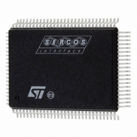
ST92F250CV2QB STMicroelectronics, ST92F250CV2QB Datasheet - Page 412

ST92F250CV2QB
Manufacturer Part Number
ST92F250CV2QB
Description
IC MCU 256K FLASH 100-PQFP
Manufacturer
STMicroelectronics
Series
ST9r
Datasheet
1.ST92F150CV1TB.pdf
(429 pages)
Specifications of ST92F250CV2QB
Core Processor
ST9
Core Size
8/16-Bit
Speed
24MHz
Connectivity
CAN, I²C, LIN, SCI, SPI
Peripherals
DMA, LVD, POR, PWM, WDT
Number Of I /o
80
Program Memory Size
256KB (256K x 8)
Program Memory Type
FLASH
Eeprom Size
1K x 8
Ram Size
8K x 8
Voltage - Supply (vcc/vdd)
4.5 V ~ 5.5 V
Data Converters
A/D 16x10b
Oscillator Type
Internal
Operating Temperature
-40°C ~ 105°C
Package / Case
100-QFP
Processor Series
ST92F25x
Core
ST9
Data Bus Width
8 bit, 16 bit
Data Ram Size
8 KB
Interface Type
CAN, I2C, SCI, SPI
Maximum Clock Frequency
24 MHz
Number Of Programmable I/os
80
Number Of Timers
5 x 16 bit
Operating Supply Voltage
4.5 V to 5.5 V
Maximum Operating Temperature
+ 105 C
Mounting Style
SMD/SMT
Development Tools By Supplier
ST92F150-EPB
Minimum Operating Temperature
- 40 C
On-chip Adc
16 bit x 10 bit
Case
QFP
Lead Free Status / RoHS Status
Lead free / RoHS Compliant
Other names
497-2139
Available stocks
Company
Part Number
Manufacturer
Quantity
Price
Company:
Part Number:
ST92F250CV2QB
Manufacturer:
HKE
Quantity:
30 000
- Current page: 412 of 429
- Download datasheet (8Mb)
ST92F124/F150/F250 - KNOWN LIMITATIONS
KNOWN LIMITATIONS (Cont’d)
13.3.3 AF bit (acknowledge failure flag) in
transmitter mode (slave and master)
Description
The AF bit is cleared by reading the I2CSR2 reg-
ister. However, if read before the completion of the
transmission, the AF flag will be set again, thus
possibly generating a new interrupt.
Workaround
Software must ensure either that the SCL line is
back at 0 before reading the SR2 register, or be
able to correctly handle a second interrupt during
the 9th pulse of a transmitted byte.
13.3.4 BUSY flag in multimaster mode
Description
The BUSY flag is NOT updated when the interface
is disabled (PE=0). This can have consequences
when operating in Multimaster mode; i.e. a second
active I2C master commencing a transfer with an
unset BUSY bit can cause a conflict resulting in
lost data.
Workaround
Check that the I2C is not busy before enabling the
I2C Multimaster cell.
412/429
1
13.3.5
multimaster mode
Description
In a Multimaster environment, when the interface
is configured in Master Receive mode it does not
perform arbitration during the reception of the Ac-
knowledge Bit. Mishandling of the ARLO bit from
the I2CSR2 register may occur when a second
master simultaneously requests the same data
from the same slave and the I2C master does not
acknowledge the data. The ARLO bit is then left at
0 instead of being set.
Workaround
None
13.3.6 BUSY flag gets cleared when BUS error
occurs
Description
BUSY bit gets cleared when the BUS error occurs
but the bus is actually BUSY (SCL line shows CLK
pulses). Contradictory, M/SL bit is unaffected on
BUS error
Workaround
If a Bus Error occurs, a Stop or a repeated Start
condition should be generated by the Master to re-
synchronize communication, get the transmission
acknowledged and the bus released for further
communication
ARLO
(arbitration
lost)
flag
in
Related parts for ST92F250CV2QB
Image
Part Number
Description
Manufacturer
Datasheet
Request
R

Part Number:
Description:
STMicroelectronics [RIPPLE-CARRY BINARY COUNTER/DIVIDERS]
Manufacturer:
STMicroelectronics
Datasheet:

Part Number:
Description:
STMicroelectronics [LIQUID-CRYSTAL DISPLAY DRIVERS]
Manufacturer:
STMicroelectronics
Datasheet:

Part Number:
Description:
BOARD EVAL FOR MEMS SENSORS
Manufacturer:
STMicroelectronics
Datasheet:

Part Number:
Description:
NPN TRANSISTOR POWER MODULE
Manufacturer:
STMicroelectronics
Datasheet:

Part Number:
Description:
TURBOSWITCH ULTRA-FAST HIGH VOLTAGE DIODE
Manufacturer:
STMicroelectronics
Datasheet:

Part Number:
Description:
Manufacturer:
STMicroelectronics
Datasheet:

Part Number:
Description:
DIODE / SCR MODULE
Manufacturer:
STMicroelectronics
Datasheet:

Part Number:
Description:
DIODE / SCR MODULE
Manufacturer:
STMicroelectronics
Datasheet:

Part Number:
Description:
Search -----> STE16N100
Manufacturer:
STMicroelectronics
Datasheet:

Part Number:
Description:
Search ---> STE53NA50
Manufacturer:
STMicroelectronics
Datasheet:

Part Number:
Description:
NPN Transistor Power Module
Manufacturer:
STMicroelectronics
Datasheet:

Part Number:
Description:
DIODE / SCR MODULE
Manufacturer:
STMicroelectronics
Datasheet:


