MPC5553MZP132 Freescale Semiconductor, MPC5553MZP132 Datasheet - Page 12
MPC5553MZP132
Manufacturer Part Number
MPC5553MZP132
Description
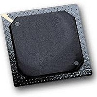
IC MCU MPC5553 REV A 416-PBGA
Manufacturer
Freescale Semiconductor
Series
MPC55xx Qorivvar
Datasheet
1.MPC5553EVBE.pdf
(68 pages)
Specifications of MPC5553MZP132
Core Processor
e200z6
Core Size
32-Bit
Speed
132MHz
Connectivity
CAN, EBI/EMI, Ethernet, SCI, SPI
Peripherals
DMA, POR, PWM, WDT
Number Of I /o
220
Program Memory Size
1.5MB (1.5M x 8)
Program Memory Type
FLASH
Ram Size
64K x 8
Voltage - Supply (vcc/vdd)
1.35 V ~ 1.65 V
Data Converters
A/D 40x12b
Oscillator Type
External
Operating Temperature
-40°C ~ 125°C
Package / Case
416-PBGA
Processor Series
MPC5xxx
Core
e200z6
Data Bus Width
32 bit
Data Ram Size
64 KB
Interface Type
7-Wire, DSPI, ESCI
Maximum Clock Frequency
132 MHz
Number Of Timers
56
Maximum Operating Temperature
+ 125 C
Mounting Style
SMD/SMT
Minimum Operating Temperature
- 40 C
For Use With
MPC5553EVBISYS - KIT EVAL ISYSTEMS MPC5553MPC5553EVBGHS - KIT EVAL GREEN HILLS SOFTWAREMPC5553EVB - KIT EVAL MPC5553MZP132MPC5553EVBE - BOARD EVAL FOR MPC5553
Lead Free Status / RoHS Status
Lead free / RoHS Compliant
Eeprom Size
-
Lead Free Status / Rohs Status
No
Available stocks
Company
Part Number
Manufacturer
Quantity
Price
Company:

Part Number:
MPC5553MZP132
Manufacturer:
Freescale Semiconductor
Quantity:
10 000


Electrical Characteristics
Table 8
pad_sh (slow type).
The values in
during power up.
Before exiting the internal POR state, the voltage on the pins goes to high-impedance until POR negates.
When the internal POR negates, the functional state of the signal during reset applies and the weak-pull
devices (up or down) are enabled as defined in the device Reference Manual. If V
propagate the logic signals, the weak-pull devices can pull the signals to V
To avoid this condition, minimize the ramp time of the V
required to enable the external circuitry connected to the device outputs.
3.7.1
When powering up the device, V
more than the V
bypass clock mode because the internal versions of PLLCFG[0:1] and RSTCFG are not powered and
therefore cannot read the default state when POR negates. V
pin (V
applies during power up only. V
3.7.2
The 1.5 V V
power supply rises above 2.0 V. This ensures that digital logic in the PLL for the 1.5 V power supply does
not begin to operate below the specified operation range lower limit of 1.35 V. Because the internal 1.5 V
POR is disabled, the internal 3.3 V POR or the RESET power POR must hold the device in reset. Since
they can negate as low as 2.0 V, V
POR negate.
12
DDEH6
gives the pin state for the sequence cases for all pins with pad type pad_mh (medium type) and
Input Value of Pins During POR Dependent on V
Power-Up Sequence (V
DD
), but cannot lag both by more than the V
Table 7
V
V
V
V
power supply must rise to 1.35 V before the 3.3 V V
Table 8. Pin Status for Medium and Slow Pads During the Power Sequence
Low
DDEH
DDEH
DDEH
DDEH
DD33
lag specification listed in
and
V
Low
V
V
—
DD
DD
DD
Table 8
Asserted
Asserted
Asserted
Negated
DD33
MPC5553 Microcontroller Data Sheet, Rev. 3.0
DD33
POR
DD
do not include the effect of the weak-pull devices on the output pins
has no lead or lag requirements when powering down.
must be within specification before the 3.3 V POR and the RESET
must not lag the latest V
Pin Status for Medium and Slow Pad Output Driver
RC33
Table
Grounded)
pad_mh (medium) pad_sh (slow)
DD33
6, spec 8. This avoids accidentally selecting the
High impedance (Hi-Z)
DD
lag specification. This V
DD33
supply to a time period less than the time
Functional
DDSYN
Low
Hi-Z
can lag V
DDSYN
or RESET power pin (V
DDE
power supply and the RESET
DDSYN
DD33
and V
DD
DD33
or the RESET power
is too low to correctly
Freescale Semiconductor
DDEH
lag specification
.
DDEH6
) by
Related parts for MPC5553MZP132
Image
Part Number
Description
Manufacturer
Datasheet
Request
R

Part Number:
Description:
Mpc5553 High Performance Microcontroller
Manufacturer:
Freescale Semiconductor, Inc
Datasheet:
Part Number:
Description:
Manufacturer:
Freescale Semiconductor, Inc
Datasheet:
Part Number:
Description:
Manufacturer:
Freescale Semiconductor, Inc
Datasheet:
Part Number:
Description:
Manufacturer:
Freescale Semiconductor, Inc
Datasheet:
Part Number:
Description:
Manufacturer:
Freescale Semiconductor, Inc
Datasheet:
Part Number:
Description:
Manufacturer:
Freescale Semiconductor, Inc
Datasheet:
Part Number:
Description:
Manufacturer:
Freescale Semiconductor, Inc
Datasheet:
Part Number:
Description:
Manufacturer:
Freescale Semiconductor, Inc
Datasheet:
Part Number:
Description:
Manufacturer:
Freescale Semiconductor, Inc
Datasheet:
Part Number:
Description:
Manufacturer:
Freescale Semiconductor, Inc
Datasheet:
Part Number:
Description:
Manufacturer:
Freescale Semiconductor, Inc
Datasheet:
Part Number:
Description:
Manufacturer:
Freescale Semiconductor, Inc
Datasheet:
Part Number:
Description:
Manufacturer:
Freescale Semiconductor, Inc
Datasheet:
Part Number:
Description:
Manufacturer:
Freescale Semiconductor, Inc
Datasheet:
Part Number:
Description:
Manufacturer:
Freescale Semiconductor, Inc
Datasheet: