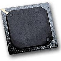
MPC5553MZP132 Freescale Semiconductor, MPC5553MZP132 Datasheet - Page 21

MPC5553MZP132
Manufacturer Part Number
MPC5553MZP132
Description
IC MCU MPC5553 REV A 416-PBGA
Manufacturer
Freescale Semiconductor
Series
MPC55xx Qorivvar
Datasheet
1.MPC5553EVBE.pdf
(68 pages)
Specifications of MPC5553MZP132
Core Processor
e200z6
Core Size
32-Bit
Speed
132MHz
Connectivity
CAN, EBI/EMI, Ethernet, SCI, SPI
Peripherals
DMA, POR, PWM, WDT
Number Of I /o
220
Program Memory Size
1.5MB (1.5M x 8)
Program Memory Type
FLASH
Ram Size
64K x 8
Voltage - Supply (vcc/vdd)
1.35 V ~ 1.65 V
Data Converters
A/D 40x12b
Oscillator Type
External
Operating Temperature
-40°C ~ 125°C
Package / Case
416-PBGA
Processor Series
MPC5xxx
Core
e200z6
Data Bus Width
32 bit
Data Ram Size
64 KB
Interface Type
7-Wire, DSPI, ESCI
Maximum Clock Frequency
132 MHz
Number Of Timers
56
Maximum Operating Temperature
+ 125 C
Mounting Style
SMD/SMT
Minimum Operating Temperature
- 40 C
For Use With
MPC5553EVBISYS - KIT EVAL ISYSTEMS MPC5553MPC5553EVBGHS - KIT EVAL GREEN HILLS SOFTWAREMPC5553EVB - KIT EVAL MPC5553MZP132MPC5553EVBE - BOARD EVAL FOR MPC5553
Lead Free Status / RoHS Status
Lead free / RoHS Compliant
Eeprom Size
-
Lead Free Status / Rohs Status
No
Available stocks
Company
Part Number
Manufacturer
Quantity
Price
Company:
Part Number:
MPC5553MZP132
Manufacturer:
Freescale Semiconductor
Quantity:
10 000
1
2
3
4
5
6
7
8
9
10
11
12
13
14
15
16
17
Freescale Semiconductor
Spec
Nominal crystal and external reference values are worst-case not more than 1%. The device operates correctly if the frequency
remains within ± 5% of the specification limit. This tolerance range allows for a slight frequency drift of the crystals over time.
The designer must thoroughly understand the drift margin of the source clock.
All internal registers retain data at 0 Hz.
Up to the maximum frequency rating of the device (refer to
Loss of reference frequency is defined as the reference frequency detected internally, which transitions the PLL into self-clocked
mode.
The PLL operates at self-clocked mode (SCM) frequency when the reference frequency falls below f
measured on the CLKOUT ball with the divider set to divide-by-two of the system clock.
NOTE: In SCM, the MFD and PREDIV have no effect and the RFD is bypassed.
Use the EXTAL input high voltage parameter when using the FlexCAN oscillator in crystal mode (no quartz crystals or
resonators). (V
Use the EXTAL input low voltage parameter when using the FlexCAN oscillator in crystal mode (no quartz crystals or
resonators). (V
I
C
This specification applies to the period required for the PLL to relock after changing the MFD frequency control bits in the
synthesizer control register (SYNCR). From power up with crystal oscillator reference, the lock time also includes the crystal
startup time.
PLL is operating in 1:1 PLL mode.
V
Jitter is the average deviation from the programmed frequency measured over the specified interval at maximum f
Measurements are made with the device powered by filtered supplies and clocked by a stable external clock signal. Noise
injected into the PLL circuitry via V
for a given interval. CLKOUT divider is set to divide-by-two.
Values are with frequency modulation disabled. If frequency modulation is enabled, jitter is the sum of (jitter + Cmod).
Modulation depth selected must not result in f
f
Maximum value for dual controller (1:1) mode is (f
xtal
sys
19
20
21
22
DDE
PCB_EXTAL
is the oscillator bias current out of the XTAL pin with both EXTAL and XTAL pins grounded.
=
= 3.0–3.6 V.
f
CLKOUT period jitter, measured at f
Frequency modulation range limit
ICO frequency
f
f
Predivider output frequency (to PLL)
ico
ico
ico
(do not exceed f
Peak-to-peak jitter (clock edge to clock edge)
Long term jitter (averaged over a 2 ms interval)
÷ (2
= [ f
= [ f
and C
RFD
ref_crystal
ref_ext
extal
xtal
)
– V
PCB_XTAL
– V
× (MFD + 4) ] ÷ (PREDIV + 1)
extal
xtal
× (MFD + 4) ] ÷ (PREDIV + 1)
sys
) must be ≥ 400 mV for the oscillator’s comparator to produce the output clock.
) must be ≥ 400 mV for the oscillator’s comparator to produce the output clock.
Characteristic
maximum)
are the measured PCB stray capacitances on EXTAL and XTAL, respectively.
Table 12. FMPLL Electrical Specifications (continued)
(V
DDSYN
DDSYN
MPC5553 Microcontroller Data Sheet, Rev. 3.0
= 3.0–3.6 V; V
15
and V
SYS
sys
SSSYN
max:
value greater than the f
MAX
13, 14
and variation in crystal oscillator frequency increase the jitter percentage
16
÷ 2) with the predivider set to 1 (FMPLL_SYNCR[PREDIV] = 0b001).
SS
= V
Table
SSSYN
Symbol
C
f
PREDIV
C
JITTER
1).
f
MOD
ico
= 0.0 V; T
sys
maximum specified value.
A
Minimum
= T
0.8
48
—
—
4
L
to T
H
)
Electrical Characteristics
Maximum
LOR
20
0.01
f
2.4
MAX
5.0
. SCM frequency is
17
sys
.
f
CLKOUT
%f
MHz
MHz
Unit
%
SYS
21


