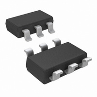
LPV531MK/NOPB National Semiconductor, LPV531MK/NOPB Datasheet - Page 12

LPV531MK/NOPB
Manufacturer Part Number
LPV531MK/NOPB
Description
IC OPAMP PROG R-R OUT TSOT23-6
Manufacturer
National Semiconductor
Series
PowerWise®r
Datasheet
1.LPV531MKNOPB.pdf
(17 pages)
Specifications of LPV531MK/NOPB
Amplifier Type
General Purpose
Number Of Circuits
1
Output Type
Rail-to-Rail
Slew Rate
2.5 V/µs
Gain Bandwidth Product
4.6MHz
Current - Input Bias
0.05pA
Voltage - Input Offset
1000µV
Current - Supply
425µA
Current - Output / Channel
24mA
Voltage - Supply, Single/dual (±)
2.7 V ~ 5.5 V
Operating Temperature
-40°C ~ 85°C
Mounting Type
Surface Mount
Package / Case
TSOT-23-6, TSOT-6
Number Of Channels
1
Voltage Gain Db
128 dB
Common Mode Rejection Ratio (min)
72 dB
Input Offset Voltage
4.5 mV at 5 V
Operating Supply Voltage
5 V
Supply Current
0.53 mA at 5 V
Maximum Operating Temperature
+ 85 C
Minimum Operating Temperature
- 40 C
Lead Free Status / RoHS Status
Lead free / RoHS Compliant
-3db Bandwidth
-
Lead Free Status / Rohs Status
Details
Other names
LPV531MK
LPV531MKTR
LPV531MKTR
www.national.com
Application Information
The LPV531 is an extremely versatile operational amplifier
because performance and power consumption can be ad-
justed during operation. This provides a method to dynami-
cally optimize the supply current, the bandwidth and the
output short circuit current in the application. The power level
can be set by the current drawn from the I
to the application performance requirements.
CIRCUIT TOPOLOGY
As shown in Figure 1, the LPV531 contains two internal bias
reference generators that deliver a reference current (I
to the amplifier core. The programmable bias generator gen-
POWER MODE CONTROL
To illustrate typical configurations three possible solutions to
control the power mode(s) of the LPV531 will be described.
1. Single Power Mode
If the application requires one single power mode for the
LPV531, then the easiest way to achieve this is to connect a
resistor (R
internal circuitry, R
the I
internal
V
For a desired supply current, bandwidth, short circuit current,
or load resistance, the required value of R
lated using the equations in the section “DETERMINING
THE I
INT
SEL
= 110 mV. This set up is illustrated in Figure 2.
SEL
pin. Internally the I
series
LEVELS”.
EXT
) from the I
resistor
EXT
will determine the current drawn from
SEL
SEL
(R
INT
pin to V
pin is connected to an 11 kΩ
)
which
−
. Together with the
EXT
SEL
is
FIGURE 1. Simplified Schematic
can be calcu-
pin according
biased
REF
at
)
12
erates a 110 mV reference voltage (V
voltage is converted into a programmable reference current
(I
resistor (R
added to the output current from the low power bias genera-
tor (I
zero and the I
that in this mode the power supply current is below 1 µA. In
this 1 µA power mode, the LPV531 is functional but perfor-
mance over the full temperature range is not guaranteed.
The 1 µA power mode operation is only recommended for
applications with a temperature range between 0 and 70˚C.
PROG
STDB
) through the internal resistor (R
). When the I
EXT
FIGURE 2. Single Power Mode
) connected to the I
REF
equals I
SEL
STDB
pin is left floating, I
. The value of I
SEL
pin. Internally, I
INT
INT
) and the external
). This reference
STDB
PROG
20132336
20132337
PROG
is such
equals
is


