ST16C2552IJ44-F Exar Corporation, ST16C2552IJ44-F Datasheet - Page 3
ST16C2552IJ44-F
Manufacturer Part Number
ST16C2552IJ44-F
Description
IC UART FIFO 16B DUAL 44PLCC
Manufacturer
Exar Corporation
Type
RS- 232 or RS- 485r
Specifications of ST16C2552IJ44-F
Number Of Channels
2, DUART
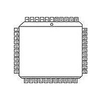
Package / Case
44-LCC (J-Lead)
Features
*
Fifo's
16 Byte
Protocol
RS232, RS485
Voltage - Supply
3.3 V ~ 5 V
With False Start Bit Detection
Yes
With Modem Control
Yes
With Cmos
Yes
Mounting Type
Surface Mount
Data Rate
4 Mbps
Supply Voltage (max)
5.5 V
Supply Voltage (min)
2.97 V
Supply Current
3 mA
Maximum Operating Temperature
+ 85 C
Minimum Operating Temperature
- 40 C
Mounting Style
SMD/SMT
Operating Supply Voltage
3.3 V or 5 V
No. Of Channels
2
Supply Voltage Range
2.97V To 5.5V
Operating Temperature Range
-40°C To +85°C
Digital Ic Case Style
PLCC
No. Of Pins
44
Filter Terminals
SMD
Rohs Compliant
Yes
Lead Free Status / RoHS Status
Lead free / RoHS Compliant
Lead Free Status / RoHS Status
Lead free / RoHS Compliant, Lead free / RoHS Compliant
Other names
1016-1258-5
Available stocks
Company
Part Number
Manufacturer
Quantity
Price
Company:

Part Number:
ST16C2552IJ44-F
Manufacturer:
Exar Corporation
Quantity:
135
Company:
Part Number:
ST16C2552IJ44-F
Manufacturer:
IDT
Quantity:
4 795
Company:
Part Number:
ST16C2552IJ44-F
Manufacturer:
Exar Corporation
Quantity:
10 000


REV. 4.2.2
PIN DESCRIPTIONS
Pin Description
DATA BUS INTERFACE
MODEM OR SERIAL I/O INTERFACE
TXRDYB#
TXRDYA#
CHSEL
N
IOW#
IOR#
INTB
INTA
CS#
D7
D6
D5
D4
D3
D2
D1
D0
A2
A1
A0
AME
44-PLCC
P
15
14
10
24
20
18
16
34
17
32
IN
9
8
7
6
5
4
3
2
1
#
T
I/O
YPE
O
O
O
O
I
I
I
I
I
UART channel A Transmitter Ready (active low). The output provides the TX
FIFO/THR status for transmit channel A.
unconnected.
Address data lines [2:0]. These 3 address lines select one of the internal registers in
UART channel A/B during a data bus transaction.
Data bus lines [7:0] (bidirectional).
Input/Output Read Strobe (active low). The falling edge instigates an internal read
cycle and retrieves the data byte from an internal register pointed to by the address
lines [A2:A0]. The data byte is placed on the data bus to allow the host processor to
read it on the rising edge.
Input/Output Write Strobe (active low). The falling edge instigates an internal write
cycle and the rising edge transfers the data byte on the data bus to an internal regis-
ter pointed by the address lines.
UART chip select (active low). This function selects channel A or B in accordance
with the logical state of the CHSEL pin. This allows data to be transferred between
the user CPU and the 2552.
Channel Select - UART channel A or B is selected by the logical state of this pin when
the CS# pin is a logic 0. A logic 0 on the CHSEL selects the UART channel B while a
logic 1 selects UART channel A. Normally, CHSEL could just be an address line from
the user CPU such as A3. Bit-0 of the Alternate Function Register (AFR) can tempo-
rarily override CHSEL function, allowing the user to write to both channel register
simultaneously with one write cycle when CS# is low. It is especially useful during the
initialization routine.
UART channel A Interrupt output (active high). A logic high indicates channel A is
requesting for service. For more details, see Figures
UART channel B Interrupt output (active high). A logic high indicates channel B is
requesting for service. For more details, see Figures
UART channel B Transmitter Ready (active low). The output provides the TX FIFO/
THR status for transmit channel B. If it is not used, leave it unconnected.
3
2.97V TO 5.5V DUAL UART WITH 16-BYTE FIFO
D
ESCRIPTION
If it is not used, leave it
16
16
-
-
21
21
.
.
ST16C2552
Related parts for ST16C2552IJ44-F
Image
Part Number
Description
Manufacturer
Datasheet
Request
R

Part Number:
Description:
2.97V TO 5.5V DUAL UART WITH 16-BYTE FIFO
Manufacturer:
Exar Corporation
Part Number:
Description:
BiCMOS Fixed, Quad, Voltage Output, Single or Dual Supply 8-Bit Digital-to-Analog Converter
Manufacturer:
Exar Corporation
Datasheet:
Part Number:
Description:
Manufacturer:
Exar Corporation
Datasheet:
Part Number:
Description:
Voltage-Controlled Oscillator
Manufacturer:
Exar Corporation
Datasheet:
Part Number:
Description:
INTEGRATED LINE TRANSMITTER
Manufacturer:
Exar Corporation
Datasheet:
Part Number:
Description:
Monolithic Function Generator
Manufacturer:
Exar Corporation
Datasheet:
Part Number:
Description:
CMOS Microprocessor Compatible Double-Buffered 12-Bit Digital-to-Analog Converter
Manufacturer:
Exar Corporation
Datasheet:
Part Number:
Description:
CMOS 6 BIT HIGH SPEED ANALOG TO DIGITAL CONVERTER
Manufacturer:
Exar Corporation
Datasheet:
Part Number:
Description:
Manufacturer:
Exar Corporation
Datasheet:
Part Number:
Description:
Manufacturer:
Exar Corporation
Datasheet:
Part Number:
Description:
8-Channel, Voltage Output 10 MHz Input Bandwidth 8-Bit Multiplying DACs with Serial Digital Data Por
Manufacturer:
Exar Corporation
Datasheet:
Part Number:
Description:
15 V CMOS Multiplying10-Bit Digital-to-Analog Converter
Manufacturer:
Exar Corporation
Datasheet:
Part Number:
Description:
Monolithic Function Generator
Manufacturer:
Exar Corporation
Datasheet: