TWR-K60N512-KIT Freescale Semiconductor, TWR-K60N512-KIT Datasheet - Page 10
TWR-K60N512-KIT
Manufacturer Part Number
TWR-K60N512-KIT
Description
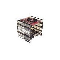
TOWER SYSTEM KIT K60N512
Manufacturer
Freescale Semiconductor
Series
Kinetisr
Type
MCUr
Specifications of TWR-K60N512-KIT
Contents
4 Boards, Documentation, DVD
Processor To Be Evaluated
K60
Data Bus Width
32 bit
Interface Type
RS-232, USB, CAN, I2C, SPI, UART
Dimensions
3.5 in x 3.5 in x 3.5 in
Operating Supply Voltage
1.71 V to 3.6 V
Silicon Manufacturer
Freescale
Core Architecture
ARM
Core Sub-architecture
Cortex - M4
Silicon Core Number
MK
Silicon Family Name
Kinetis - K60
Kit Contents
4x Brds, Cable, Docs
Rohs Compliant
Yes
For Use With/related Products
Freescale Tower System, K60N512
Lead Free Status / RoHS Status
Lead free / RoHS Compliant


Note: Many of the trace signals connected to the debug connector are also connected elsewhere on
the TWR-K60N512. Refer to Table 6 “I/O Connectors and Pin Usage Table” and Table 7 “TWR-K60N512
Primary Connector Pinout” for more information.
2.5 Infrared Port
An infrared transmit and receive interface is implemented as shown in Figure 5 below. The CMT_IRO
pin directly drives an infrared diode. The receiver uses an infrared phototransistor connected to an on-
chip analog comparator through a low-pass filter. Internal to the K60 device, the output of the analog
comparator can be routed to a UART module for easier processing of the incoming data stream.
2.6 Accelerometer
An MMA7660 digital accelerometer is connected to the K60 MCU through an I2C interface and a
GPIO/IRQ signal. Refer to Table 6 “I/O Connectors and Pin Usage Table” for connection details.
2.7 Potentiometer, Pushbuttons, LEDs
The TWR-K60N512 features two pushbutton switches connected to GPIO/interrupt signals, one
pushbutton connected to the master reset signal, four capacitive touch pad electrodes, four user-
controllable LEDs, and a potentiometer connected to an ADC input signal. Refer to Table 6 “I/O
Connectors and Pin Usage Table” for information about which port pins are connected to these
features.
2.8 General Purpose Tower Plug-in (TWRPI) Socket
The TWR-K60N512 features a socket that can accept a variety of different Tower Plug-in modules
featuring sensors, RF transceivers, and more. The General Purpose TWRPI socket provides access to
Pin
20
PTD7
TRACEDATA[3]
TWR-K60N512 Tower Module User's Manual
Function
CMT_IRO
P3V3
Default: no shunt
(Disable IRDA)
Figure 5. Infrared Port Implementation
Q3
QTLP610CPD
R24
1.54K
J6
IRDA_SEN
HDR 1X2 TH
PTA7/FTM0_CH4/TRACE_D3
R25
1.0K
IRDAJ
2
TWR-K60N512 Connection
D3
QTLP610CIR
CMP0_IN0
C5
0.1UF
1
IRDAR
PTC6
R23
33
Page 10 of 17
Related parts for TWR-K60N512-KIT
Image
Part Number
Description
Manufacturer
Datasheet
Request
R

Part Number:
Description:
Manufacturer:
Freescale Semiconductor, Inc
Datasheet:
Part Number:
Description:
Manufacturer:
Freescale Semiconductor, Inc
Datasheet:
Part Number:
Description:
Manufacturer:
Freescale Semiconductor, Inc
Datasheet:
Part Number:
Description:
Manufacturer:
Freescale Semiconductor, Inc
Datasheet:
Part Number:
Description:
Manufacturer:
Freescale Semiconductor, Inc
Datasheet:
Part Number:
Description:
Manufacturer:
Freescale Semiconductor, Inc
Datasheet:
Part Number:
Description:
Manufacturer:
Freescale Semiconductor, Inc
Datasheet:
Part Number:
Description:
Manufacturer:
Freescale Semiconductor, Inc
Datasheet:
Part Number:
Description:
Manufacturer:
Freescale Semiconductor, Inc
Datasheet:
Part Number:
Description:
Manufacturer:
Freescale Semiconductor, Inc
Datasheet:
Part Number:
Description:
Manufacturer:
Freescale Semiconductor, Inc
Datasheet:
Part Number:
Description:
Manufacturer:
Freescale Semiconductor, Inc
Datasheet:
Part Number:
Description:
Manufacturer:
Freescale Semiconductor, Inc
Datasheet:
Part Number:
Description:
Manufacturer:
Freescale Semiconductor, Inc
Datasheet:
Part Number:
Description:
Manufacturer:
Freescale Semiconductor, Inc
Datasheet: