TWR-K60N512-KIT Freescale Semiconductor, TWR-K60N512-KIT Datasheet - Page 13
TWR-K60N512-KIT
Manufacturer Part Number
TWR-K60N512-KIT
Description
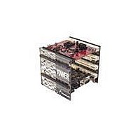
TOWER SYSTEM KIT K60N512
Manufacturer
Freescale Semiconductor
Series
Kinetisr
Type
MCUr
Specifications of TWR-K60N512-KIT
Contents
4 Boards, Documentation, DVD
Processor To Be Evaluated
K60
Data Bus Width
32 bit
Interface Type
RS-232, USB, CAN, I2C, SPI, UART
Dimensions
3.5 in x 3.5 in x 3.5 in
Operating Supply Voltage
1.71 V to 3.6 V
Silicon Manufacturer
Freescale
Core Architecture
ARM
Core Sub-architecture
Cortex - M4
Silicon Core Number
MK
Silicon Family Name
Kinetis - K60
Kit Contents
4x Brds, Cable, Docs
Rohs Compliant
Yes
For Use With/related Products
Freescale Tower System, K60N512
Lead Free Status / RoHS Status
Lead free / RoHS Compliant


2.11 USB
The K60N512 features a USB full-speed/low-speed OTG/Host/Device controller with built-in
transceiver. The TWR-K60N512 routes the USB D+ and D- signals from the K60 MCU to the Primary
Connector, allowing the connection to external USB connectors or additional circuitry on a Tower
peripheral module.
The TWR-SER module included as part of the TWR-K60N512-KIT provides a USB OTG/Host/Device
interface with a mini-AB USB connector. There are many configuration options that can be selected to
evaluate different USB modes of operation. By default, the TWR-SER is configured for USB Device
operation. Please refer to the documentation included with the TWR-SER for more information on the
configuration options.
2.12 Secure Digital Card Slot
A Secure Digital (SD) card slot is available on the TWR-K60N512 connected to the SD Host Controller
(SDHC) signals of the K60 MCU. This slot will accept SD memory cards as well as Secure Digital Input
Output (SDIO) cards. Refer to Table 6 “I/O Connectors and Pin Usage Table” for the SDHC signal
connection details.
2.13 External Bus Interface – FlexBus
The K60 device features a multi-function external bus interface called the FlexBus interface controller
capable of interfacing to slave-only devices. The FlexBus interface is not used directly on the TWR-
K60N512. Instead, a subset of the FlexBus is connected to the Primary Connector so that the external
bus can access devices on Tower peripheral modules. Refer to Table 7 “TWR-K60N512 Primary
Connector Pinout” and sheet 8 of the TWR-K60N512 schematics for more details.
3 Jumper Table
There are several jumpers on the TWR-K60N512 that provide configuration selection and signal
isolation. Refer to the following table for details. The default installed jumper settings are shown in
bold with asterisks.
Jumper
J1
J2
J6
J8
USB VREGIN Power
Connection
Infrared Transmitter
Connection
Clock Input Source
Selection
MCU Power Connection
Option
TWR-K60N512 Tower Module User's Manual
Table 5. TWR-K60N512 Jumper Table
Setting
*OFF*
*ON*
*1-2*
*ON*
OFF
OFF
ON
2-3
Connect USB0_VBUS from Primary Elevator (A57) to
VREGIN
Disconnect VREGIN from Primary Elevator
Connect PTD7/CMT_IRO/UART0_TX to IR Transmitter (D1)
Disconnect PTD7/CMT_IRO/UART0_TX from IR Transmitter
(D1)
Connect main EXTAL to on-board 50 MHz clock
Connect EXTAL to CLKIN0 signal on Primary Elevator (B24)
Connect on-board 3.3V supply to MCU
Isolate MCU from power supply (allows for external supply
or power measurements)
Description
Page 13 of 17
Related parts for TWR-K60N512-KIT
Image
Part Number
Description
Manufacturer
Datasheet
Request
R

Part Number:
Description:
Manufacturer:
Freescale Semiconductor, Inc
Datasheet:
Part Number:
Description:
Manufacturer:
Freescale Semiconductor, Inc
Datasheet:
Part Number:
Description:
Manufacturer:
Freescale Semiconductor, Inc
Datasheet:
Part Number:
Description:
Manufacturer:
Freescale Semiconductor, Inc
Datasheet:
Part Number:
Description:
Manufacturer:
Freescale Semiconductor, Inc
Datasheet:
Part Number:
Description:
Manufacturer:
Freescale Semiconductor, Inc
Datasheet:
Part Number:
Description:
Manufacturer:
Freescale Semiconductor, Inc
Datasheet:
Part Number:
Description:
Manufacturer:
Freescale Semiconductor, Inc
Datasheet:
Part Number:
Description:
Manufacturer:
Freescale Semiconductor, Inc
Datasheet:
Part Number:
Description:
Manufacturer:
Freescale Semiconductor, Inc
Datasheet:
Part Number:
Description:
Manufacturer:
Freescale Semiconductor, Inc
Datasheet:
Part Number:
Description:
Manufacturer:
Freescale Semiconductor, Inc
Datasheet:
Part Number:
Description:
Manufacturer:
Freescale Semiconductor, Inc
Datasheet:
Part Number:
Description:
Manufacturer:
Freescale Semiconductor, Inc
Datasheet:
Part Number:
Description:
Manufacturer:
Freescale Semiconductor, Inc
Datasheet: