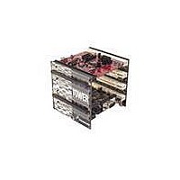
TWR-K60N512-KIT Freescale Semiconductor, TWR-K60N512-KIT Datasheet - Page 7

TWR-K60N512-KIT
Manufacturer Part Number
TWR-K60N512-KIT
Description
TOWER SYSTEM KIT K60N512
Manufacturer
Freescale Semiconductor
Series
Kinetisr
Type
MCUr
Specifications of TWR-K60N512-KIT
Contents
4 Boards, Documentation, DVD
Processor To Be Evaluated
K60
Data Bus Width
32 bit
Interface Type
RS-232, USB, CAN, I2C, SPI, UART
Dimensions
3.5 in x 3.5 in x 3.5 in
Operating Supply Voltage
1.71 V to 3.6 V
Silicon Manufacturer
Freescale
Core Architecture
ARM
Core Sub-architecture
Cortex - M4
Silicon Core Number
MK
Silicon Family Name
Kinetis - K60
Kit Contents
4x Brds, Cable, Docs
Rohs Compliant
Yes
For Use With/related Products
Freescale Tower System, K60N512
Lead Free Status / RoHS Status
Lead free / RoHS Compliant
debug interface and a power supply input through a single USB mini-AB connector. Figure 4 shows a
block diagram of the TWR-K60N512. The following sections describe the hardware in more detail.
2.1 K60N512 Microcontroller
The TWR-K60N512 module features the MK60N512VMD100. The K60 microcontroller family is part of
the Kinetis portfolio of devices built around an ARM Cortex-M4 core. Refer to the K60 Family Product
Brief and the K60 Family Reference Manual for comprehensive information on the MK60N512VMD100
device. The key features are listed here:
SD Card Slot
Battery
32-bit ARM Cortex-M4 core with DSP instructions
100MHz maximum core operating frequency
144 MAPBGA, 13mm x 13mm, 1.0mm pitch package
1.71V – 3.6V operating voltage input range
256 Kbytes of program flash, 64 Kbytes of static RAM
FlexMemory consisting of 256 Kbytes of FlexNVM (non-volatile flash memory that can be used
as program flash, data flash, backup EEPROM of variable endurance and size) and 4 Kbytes of
FlexRAM (RAM memory that can be used as traditional RAM, as high-endurance EEPROM
storage, or flash programming acceleration RAM)
External bus interface
Power management controller with 10 different power modes
Multi-purpose clock generator with PLL and FLL operation modes
16-bit SAR ADC, 12-bit DAC
Holder
Mini-B
5.0V
5.0V
USB
Freescale Device
SDHC
JTAG, Power, SCI
OSJTAG
VBAT (RTC)
TWR-K60N512 Tower Module User's Manual
General Purpose
Tower Plug-in
SDHC, I
(TWRPI)
External Connectors
2
Figure 4. TWR-K60N512 Block Diagram
S, SPI, I
SPI, I
JTAG
SCI
50 MHz OSC
2
C, ADC, GPIO
Tower Elevator Expansion Connectors
2
C, ADC, USB, DAC, PWM, UARTs, Flexbus, Ethernet
MMA7660
144 MAPBGA
K60N512
Interface Circuits
32.768 KHz XTAL
Comparator
IR Output
TSI, GPIO
GPIO / Interrupts
Power
Reset
Page 7 of 17
Touch Tower Plug-in
Infrared Port
(TWRPI)
Capacitive
Touch
LED
LED
LED
LED
Pads
3.3V


