TWR-K60N512-KIT Freescale Semiconductor, TWR-K60N512-KIT Datasheet - Page 9
TWR-K60N512-KIT
Manufacturer Part Number
TWR-K60N512-KIT
Description
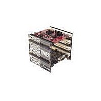
TOWER SYSTEM KIT K60N512
Manufacturer
Freescale Semiconductor
Series
Kinetisr
Type
MCUr
Specifications of TWR-K60N512-KIT
Contents
4 Boards, Documentation, DVD
Processor To Be Evaluated
K60
Data Bus Width
32 bit
Interface Type
RS-232, USB, CAN, I2C, SPI, UART
Dimensions
3.5 in x 3.5 in x 3.5 in
Operating Supply Voltage
1.71 V to 3.6 V
Silicon Manufacturer
Freescale
Core Architecture
ARM
Core Sub-architecture
Cortex - M4
Silicon Core Number
MK
Silicon Family Name
Kinetis - K60
Kit Contents
4x Brds, Cable, Docs
Rohs Compliant
Yes
For Use With/related Products
Freescale Tower System, K60N512
Lead Free Status / RoHS Status
Lead free / RoHS Compliant


VBAT. The TWR-K60N512 provides a battery holder for a coin cell battery that can be used as the VBAT
supply. The holder can accept common 20mm diameter 3V lithium coin cell batteries (e.g. 2032,
2025). Refer to the description J9 in Table 5 “TWR-K60N512 Jumper Table” for more information.
2.4 Debug Interface
There are two debug interface options provided: the on-board OSJTAG circuit and an external Cortex
Debug+ETM connector.
2.4.1 OSJTAG
An on-board MC9S08JM60 based Open Source JTAG (OSJTAG) circuit provides a JTAG debug interface
to the K60N512. A standard USB A male to Mini-B male cable (provided) can be used for debugging via
the USB connector, J16. The OSJTAG interface also provides a USB to serial bridge. Drivers for the
OSJTAG interface are provided in the P&E Micro Kinetis Tower Toolkit (available on the included DVD).
Note: The port pins connected to the OSJTAG USB-to-serial bridge (PTD6 and PTD7) are also connected
to the infrared interface. Refer to Table 6 “I/O Connectors and Pin Usage Table” and Table 5 “TWR-
K60N512 Jumper Table” for more information.
2.4.2 Cortex Debug+ETM Connector
The Cortex Debug+ETM connector is a 20-pin (0.05") connector providing access to the SWD, SWV,
JTAG, cJTAG, EzPort and ETM trace (4-bit) signals available on the K60 device. The pinout and K60 pin
connections to the debug connector, J14, is shown in Table 1Table 1.
Pin
10
11
12
13
14
15
16
17
18
19
1
2
3
4
5
6
7
8
9
VTref
TMS / SWDIO
GND
TCK / SWCLK
GND
TDO / SWO
Key
TDI
GNDDetect
nRESET
Target Power
TRACECLK
Target Power
TRACEDATA[0]
GND
TRACEDATA[1]
GND
TRACEDATA[2]
GND
TWR-K60N512 Tower Module User's Manual
Function
Table 1. Cortex Debug+ETM Connector Pinout
3.3V MCU supply (P3V3_MCU)
PTA3/SCI0_RTS_b/FTM0_CH0/JTAG_MS/SWD_DIO
GND
PTA0/SCI0_CTS_b/FTM0_CH5/JTAG_CLK/SWD_CLK/EZP_CLK
GND
PTA2/SCI0_TX/FTM0_CH7/JTAG_DO/TRACE_SWO/EZP_DO
―
PTA1/SCI0_RX/FTM0_CH6/JTAG_DI/EZP_DI
PTA4/FTM0_CH1/MS/NMI_b/EZP_CS_b
RESET_b
5V supply (via J12)
PTA6/FTM0_CH3/TRACE_CLKOUT
5V supply (via J12)
PTA10/FTM2_CH0/FTM2_QD_PHA/TRACE_D0
GND
PTA9/FTM1_CH1/FTM1_QD_PHB/TRACE_D1
GND
PTA8/FTM1_CH0/FTM1_QD_PHA/TRACE_D2
GND
TWR-K60N512 Connection
Page 9 of 17
Related parts for TWR-K60N512-KIT
Image
Part Number
Description
Manufacturer
Datasheet
Request
R

Part Number:
Description:
Manufacturer:
Freescale Semiconductor, Inc
Datasheet:
Part Number:
Description:
Manufacturer:
Freescale Semiconductor, Inc
Datasheet:
Part Number:
Description:
Manufacturer:
Freescale Semiconductor, Inc
Datasheet:
Part Number:
Description:
Manufacturer:
Freescale Semiconductor, Inc
Datasheet:
Part Number:
Description:
Manufacturer:
Freescale Semiconductor, Inc
Datasheet:
Part Number:
Description:
Manufacturer:
Freescale Semiconductor, Inc
Datasheet:
Part Number:
Description:
Manufacturer:
Freescale Semiconductor, Inc
Datasheet:
Part Number:
Description:
Manufacturer:
Freescale Semiconductor, Inc
Datasheet:
Part Number:
Description:
Manufacturer:
Freescale Semiconductor, Inc
Datasheet:
Part Number:
Description:
Manufacturer:
Freescale Semiconductor, Inc
Datasheet:
Part Number:
Description:
Manufacturer:
Freescale Semiconductor, Inc
Datasheet:
Part Number:
Description:
Manufacturer:
Freescale Semiconductor, Inc
Datasheet:
Part Number:
Description:
Manufacturer:
Freescale Semiconductor, Inc
Datasheet:
Part Number:
Description:
Manufacturer:
Freescale Semiconductor, Inc
Datasheet:
Part Number:
Description:
Manufacturer:
Freescale Semiconductor, Inc
Datasheet: