20-101-1207 Rabbit Semiconductor, 20-101-1207 Datasheet - Page 95
20-101-1207
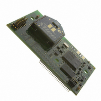
Manufacturer Part Number
20-101-1207
Description
RCM4510W FCC CERTIFIED
Manufacturer
Rabbit Semiconductor
Type
Transceiver, 802.15.4/ZigBeer
Datasheet
1.20-101-1207.pdf
(118 pages)
Specifications of 20-101-1207
Frequency
2.4GHz
Wireless Frequency
29.49 MHz
For Use With/related Products
RCM4510W
Lead Free Status / RoHS Status
Lead free / RoHS Compliant
Other names
316-1144


B.4 Using the Prototyping Board
The Prototyping Board is actually both a demonstration board and a prototyping board. As
a demonstration board, it can be used to demonstrate the functionality of the RCM4510W
right out of the box without any modifications to either board.
The Prototyping Board comes with the basic components necessary to demonstrate the
operation of the RCM4510W. Two LEDs (DS2 and DS3) are connected to PB2 and PB3,
and two switches (S2 and S3) are connected to PB4 and PB5 to demonstrate the interface
to the Rabbit 4000 microprocessor. Reset switch S1 is the hardware reset for the
RCM4510W.
The Prototyping Board provides the user with RCM4510W connection points brought out
conveniently to labeled points at header J2 on the Prototyping Board. Although header J2
is unstuffed, a 2 × 25 header is included in the bag of parts. RS-232 signals (Serial Ports C
and D) are available on header J4. A header strip at J4 allows you to connect a ribbon cable,
and a ribbon cable to DB9 connector is included with the Development Kit. The pinouts for
these locations are shown in Figure B-4.
Figure B-4. Prototyping Board Pinout
Although analog signals are shown for labeled points at header location J3 on the
Prototyping Board, the analog signals on the RCM4510W are associated with the XBee
RF module. These analog signals are not brought out to the Prototyping Board.
User’s Manual
89
Related parts for 20-101-1207
Image
Part Number
Description
Manufacturer
Datasheet
Request
R

Part Number:
Description:
COMPUTER SGL-BRD BL2500 29.4MHZ
Manufacturer:
Rabbit Semiconductor
Datasheet:

Part Number:
Description:
COMPUTER SGL-BRD BL2500 29.4MHZ
Manufacturer:
Rabbit Semiconductor
Datasheet:

Part Number:
Description:
DISPLAY GRAPHIC 12KEY PROG OP670
Manufacturer:
Rabbit Semiconductor
Datasheet:
Part Number:
Description:
DISPLAY GRAPHIC 12KEY ETH OP6700
Manufacturer:
Rabbit Semiconductor
Datasheet:

Part Number:
Description:
COMPUTER SINGLE-BOARD BL2030
Manufacturer:
Rabbit Semiconductor
Part Number:
Description:
COMPUTER SGL-BOARD ETH BL2010
Manufacturer:
Rabbit Semiconductor

Part Number:
Description:
MODULE OP6810 W/O ETH/MEM EXPANS
Manufacturer:
Rabbit Semiconductor
Datasheet:
Part Number:
Description:
COMPUTER SINGLE-BOARD BL2020
Manufacturer:
Rabbit Semiconductor
Part Number:
Description:
COMPUTER BL2010 W/FRICTION LOCK
Manufacturer:
Rabbit Semiconductor
Part Number:
Description:
COMPUTER BL2020 W/FRICTION LOCK
Manufacturer:
Rabbit Semiconductor
Part Number:
Description:
COMPUTER SGL-BRD BL2500 44.2MHZ
Manufacturer:
Rabbit Semiconductor
Datasheet:
Part Number:
Description:
COMPUTER SGL-BOARD FULL BL2000
Manufacturer:
Rabbit Semiconductor

Part Number:
Description:
COMPUTER SINGLE-BOARD BL2110
Manufacturer:
Rabbit Semiconductor

Part Number:
Description:
COMPUTER SGL-BRD 29.4MHZ BL2610
Manufacturer:
Rabbit Semiconductor
Datasheet:
Part Number:
Description:
INTERFACE OP6800 512K FLASH&SRAM
Manufacturer:
Rabbit Semiconductor
Datasheet: