ATAKSTK511-3 Atmel, ATAKSTK511-3 Datasheet - Page 11
ATAKSTK511-3
Manufacturer Part Number
ATAKSTK511-3
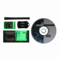
Description
KIT RF MODULE 315MHZ FOR STK500
Manufacturer
Atmel
Series
SmartRF®r
Type
Transmitter, Receiver, ASK, FSKr
Specifications of ATAKSTK511-3
Frequency
433MHz
Wireless Frequency
315 MHz
For Use With/related Products
ATSTK500
Lead Free Status / RoHS Status
Contains lead / RoHS non-compliant
Other names
Q2262874


3.2
3.2.1
3.2.2
STK511 User Guide
Software Description
Overview
Sample Software
Decoding of the incoming digital signal from the receiver is performed by the AT90S8515 microcontroller
onboard the STK500 in socket SCKT3000D3. The demodulated RF signal present on the receiver DATA
line is routed to bit 4 of PortB. Also the D_CLK (Data Clock) line, provided by the RF receiver, is routed
to bit 2 of PortB. For this demo, the RF signal is in Manchester format.
It is possible to decode the data by measuring edge-to-edge timing of this line, but many Atmel receivers
simplify this task by recovering the clock from the DATA signal. This clock can be found on the D_CLK
line and will only appear when a predefined number of logic 1s (set in the OPMODE register under Bit
Check) are followed by a logic 0. This logic 0 is considered the start bit and from this point forward the
D_CLK line will provide a low going pulse for each data bit. The decoding microcontroller watches for
these data clock pulses and records the state of the DATA line at each occurrence. The logic state of the
DATA line following each clock pulse signifies the bit value.
Three 8-bit registers are reserved for buffering the incoming data. As the demodulated signal is received
and decoded, as described above, it is loaded into these registers. Once this is complete, the three
received bytes are compared to each other. For the received data to be considered valid at least two of
the three received bytes must match. This redundancy improves system integrity.
A valid message results in the display of data on the LEDs of the STK500 board.
Below is a sample of the Demo Receive Software that decodes the incoming demodulated signal:
/*********************************************
Function : CheckRX
Date
Author
Company : Atmel
Comments: Decode logic for incoming demodulated signal
*********************************************/
void CheckRX(void)
{
// Initialize variables
int timeOut = 0, timeOutVal = 1000, i, j;
int flag1 = 0, flag2 = 0;
// Look for D_CLK to begin pulse. This is for the start bit
while(!flag1 && timeOut < timeOutVal)
{
}
: 6/22/2004
: Toby Prescott
// Check D_CLK. Exit when low
if(PINB.2 == 0){flag1 = 1;}
// Increment timeout
else if(PINB.2 == 1){timeOut++;}
STK511 Receiver Board
4842B–AVR–10/09
3-3
Related parts for ATAKSTK511-3
Image
Part Number
Description
Manufacturer
Datasheet
Request
R

Part Number:
Description:
DEV KIT FOR AVR/AVR32
Manufacturer:
Atmel
Datasheet:

Part Number:
Description:
INTERVAL AND WIPE/WASH WIPER CONTROL IC WITH DELAY
Manufacturer:
ATMEL Corporation
Datasheet:
Part Number:
Description:
Low-Voltage Voice-Switched IC for Hands-Free Operation
Manufacturer:
ATMEL Corporation
Datasheet:
Part Number:
Description:
MONOLITHIC INTEGRATED FEATUREPHONE CIRCUIT
Manufacturer:
ATMEL Corporation
Datasheet:
Part Number:
Description:
AM-FM Receiver IC U4255BM-M
Manufacturer:
ATMEL Corporation
Datasheet:
Part Number:
Description:
Monolithic Integrated Feature Phone Circuit
Manufacturer:
ATMEL Corporation
Datasheet:
Part Number:
Description:
Multistandard Video-IF and Quasi Parallel Sound Processing
Manufacturer:
ATMEL Corporation
Datasheet:
Part Number:
Description:
High-performance EE PLD
Manufacturer:
ATMEL Corporation
Datasheet:
Part Number:
Description:
8-bit Flash Microcontroller
Manufacturer:
ATMEL Corporation
Datasheet:
Part Number:
Description:
2-Wire Serial EEPROM
Manufacturer:
ATMEL Corporation
Datasheet: