ATAKSTK511-3 Atmel, ATAKSTK511-3 Datasheet - Page 7
ATAKSTK511-3
Manufacturer Part Number
ATAKSTK511-3
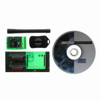
Description
KIT RF MODULE 315MHZ FOR STK500
Manufacturer
Atmel
Series
SmartRF®r
Type
Transmitter, Receiver, ASK, FSKr
Specifications of ATAKSTK511-3
Frequency
433MHz
Wireless Frequency
315 MHz
For Use With/related Products
ATSTK500
Lead Free Status / RoHS Status
Contains lead / RoHS non-compliant
Other names
Q2262874


4842B–AVR–10/09
Getting Started
2.3
2.3.1
2-2
Running the Demo
STK500 Configuration
1. Once the hardware is setup, verify that the DATA selector switch is in the STK511 position.
2. Apply power, locate the DIP switch corresponding to the OPMODE register, and set the 5th DIP
3. Press the Configure button to program the OPMODE and LIMIT registers with the selected
Now, the receiver is ready to receive an ASK (or in most cases, On-Off Keyed - OOK) signal. The
demodulated signal appears on the DATA line of the Receiver Application Board. This signal can be
routed to the on-board microcontroller or to the STK500, depending on the position of the DATA selector
switch and values of jumpers R25-R32
information).
The Transmitter Application Board contained in the evaluation kit is shipped preprogrammed with a light
intensity sensor program. It can be used with the STK500/511 Assembly to display ambient light inten-
sity using LEDs on the STK500. To run this demo it must first be properly configured.
1. Insert an AT90S8515 microcontroller into the red 40-pin socket (SCKT3000D3) on the STK500
2. Verify that the 6-pin ribbon cable is connected between the SPROG3 and the ISP6PIN headers and
3. Connect the 10-pin ribbon cable from the LEDS header to the PORTC header.
4. Apply power (12 V) to the supplied connector and turn on the STK500 power switch.
5. Connect the serial cable between RS232 CTRL and the host PC.
6. In AVR Studio, select Tools/STK500 from the menu.
7. Select the Board tab and verify that the VTARGET voltage is set to 5 V.
8. On the Program tab, select AT90S8515 from the Device pull-down menu.
9. Load the STK511 RX Decode.hex file, included on the Sample Software CD, into the field labeled
Figure 2-1.
switch to the ON position. The LED enclosed in the silkscreen legend labeled Mod should light up,
indicating a 1 (corresponding to ASK mode) was selected.
configuration.
board.
is oriented correctly.
Flash Input Hex File and press the Program button (see
Receiver Decode Software
(See “Receive Signal Routing” on page 4-6.
Figure 2-1 on page
2-2).
STK511 User Guide
for additional
Related parts for ATAKSTK511-3
Image
Part Number
Description
Manufacturer
Datasheet
Request
R

Part Number:
Description:
DEV KIT FOR AVR/AVR32
Manufacturer:
Atmel
Datasheet:

Part Number:
Description:
INTERVAL AND WIPE/WASH WIPER CONTROL IC WITH DELAY
Manufacturer:
ATMEL Corporation
Datasheet:
Part Number:
Description:
Low-Voltage Voice-Switched IC for Hands-Free Operation
Manufacturer:
ATMEL Corporation
Datasheet:
Part Number:
Description:
MONOLITHIC INTEGRATED FEATUREPHONE CIRCUIT
Manufacturer:
ATMEL Corporation
Datasheet:
Part Number:
Description:
AM-FM Receiver IC U4255BM-M
Manufacturer:
ATMEL Corporation
Datasheet:
Part Number:
Description:
Monolithic Integrated Feature Phone Circuit
Manufacturer:
ATMEL Corporation
Datasheet:
Part Number:
Description:
Multistandard Video-IF and Quasi Parallel Sound Processing
Manufacturer:
ATMEL Corporation
Datasheet:
Part Number:
Description:
High-performance EE PLD
Manufacturer:
ATMEL Corporation
Datasheet:
Part Number:
Description:
8-bit Flash Microcontroller
Manufacturer:
ATMEL Corporation
Datasheet:
Part Number:
Description:
2-Wire Serial EEPROM
Manufacturer:
ATMEL Corporation
Datasheet: