ATAKSTK511-3 Atmel, ATAKSTK511-3 Datasheet - Page 32
ATAKSTK511-3
Manufacturer Part Number
ATAKSTK511-3
Description
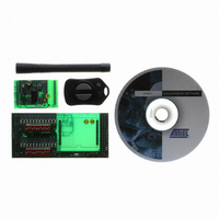
KIT RF MODULE 315MHZ FOR STK500
Manufacturer
Atmel
Series
SmartRF®r
Type
Transmitter, Receiver, ASK, FSKr
Specifications of ATAKSTK511-3
Frequency
433MHz
Wireless Frequency
315 MHz
For Use With/related Products
ATSTK500
Lead Free Status / RoHS Status
Contains lead / RoHS non-compliant
Other names
Q2262874


6.1
6.2
STK511 User Guide
General
Output Field Strength/Power
This kit is intended to showcase the broad flexibility of Atmel's RF radio chip-set by offering multiple
transmission modes that span frequencies across the RF spectrum from 315 MHz to 915 MHz. Conse-
quently, local regulatory limitations will apply that restrict certain combinations of transmission modes
and RF spectrum. These regulations generally place restrictions on carrier frequency, transmission duty
cycle, harmonic content, and method of measurement. The following paragraphs attempt to provide gen-
eral guidelines with respect to these operating parameters. The user is strongly urged to review and
understand all applicable local regulations pertaining to the implementation of the target application dur-
ing the early phases of the design process.
FCC limits transmitted RF energy to an average level, specified in terms of field strength, measured at a
distance of 3 meters from the transmitter. The averaging interval defined by the FCC is 100 ms. Through
careful selection of a transmission protocol, it is possible to utilize a transmitter that generates up to
20 dB above the FCC limit, provided the RF transmission is only active for 10 ms during any 100 ms
interval. For duty cycles greater than 10%, the duty cycle correction factor (also referred to as relaxation
factor) can be calculated as follows:
While use of this duty cycle correction factor is most often applied to OOK/ASK applications, it can also
be applied to FSK modulation and harmonic frequencies.
For 315 and 434 MHz, the limit is 6,042 and 11,000 µV/m respectively. Harmonic and other spurious
emissions must be 20 dB below the fundamental. For operation at 915 MHz, the limit increases to
50 mV/m for the fundamental and 0.5 mV/m for harmonics (50 dBc for spurious emissions). However,
field strength is no longer based on an average, which precludes the use of the duty cycle correction fac-
tor as described above. In all cases, care must be taken to insure that harmonics and spurious
emissions avoid the field strength limits that exist in the many restricted bands defined by the FCC.
For European applications, RF energy is regulated based on peak effective radiated power. Unlike the
FCC, duty cycle correction is not allowed. Peak power is limited to 10 dBm at 434 MHz and 14 dBm at
868 MHz. The European limits enable much more RF output energy than the FCC limits allow. However,
harmonics and spurious emissions restrictions are more stringent than those in the FCC's rules. They
m u s t b e k e p t b e l o w - 5 4 d B m w h e n t h e y f a l l i n t h e f o l l o w i n g b a n d s 4 7 M H z t o 7 4 M H z ,
87.5 MHz to 118 MHz, 174 MHz to 230 MHz, and 470 MHz to 862 MHz and below -36 dBm for all other
frequencies < 1 GHz. The limit relaxes further to below -30 dBm for frequencies > 1 GHz.
Correction Factor = 20log[max RF on time in ms/100 ms]
Regulatory Requirements
Section 6
4842B–AVR–10/09
6-1
Related parts for ATAKSTK511-3
Image
Part Number
Description
Manufacturer
Datasheet
Request
R

Part Number:
Description:
DEV KIT FOR AVR/AVR32
Manufacturer:
Atmel
Datasheet:

Part Number:
Description:
INTERVAL AND WIPE/WASH WIPER CONTROL IC WITH DELAY
Manufacturer:
ATMEL Corporation
Datasheet:
Part Number:
Description:
Low-Voltage Voice-Switched IC for Hands-Free Operation
Manufacturer:
ATMEL Corporation
Datasheet:
Part Number:
Description:
MONOLITHIC INTEGRATED FEATUREPHONE CIRCUIT
Manufacturer:
ATMEL Corporation
Datasheet:
Part Number:
Description:
AM-FM Receiver IC U4255BM-M
Manufacturer:
ATMEL Corporation
Datasheet:
Part Number:
Description:
Monolithic Integrated Feature Phone Circuit
Manufacturer:
ATMEL Corporation
Datasheet:
Part Number:
Description:
Multistandard Video-IF and Quasi Parallel Sound Processing
Manufacturer:
ATMEL Corporation
Datasheet:
Part Number:
Description:
High-performance EE PLD
Manufacturer:
ATMEL Corporation
Datasheet:
Part Number:
Description:
8-bit Flash Microcontroller
Manufacturer:
ATMEL Corporation
Datasheet:
Part Number:
Description:
2-Wire Serial EEPROM
Manufacturer:
ATMEL Corporation
Datasheet: