STEVAL-IHP001V3 STMicroelectronics, STEVAL-IHP001V3 Datasheet - Page 14
STEVAL-IHP001V3
Manufacturer Part Number
STEVAL-IHP001V3
Description
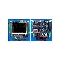
BOARD SMART PLUG STM32 SPZB260PR
Manufacturer
STMicroelectronics
Series
Zigbee™ SmartPlugr
Type
Microcontroller, Energy Meteringr
Specifications of STEVAL-IHP001V3
Frequency
2.4GHz
For Use With/related Products
STM32F10x, SPZB260-PRO, STPM01
Lead Free Status / RoHS Status
Lead free / RoHS Compliant
Other names
497-10677


Terminology
6
6.1
6.2
6.3
6.4
6.5
14/60
Terminology
Measurement error
The error associated with the energy measurement made by the STPM01 is defined as:
Percentage error = [STPM01 (reading) - true energy] / true energy
ADC offset error
This is the error due to the DC component associated with the analog inputs of the A/D
converters. Due to the internal automatic DC offset cancellation the STPM01 measurement
is not affected by DC components in voltage and current channel. The DC offset
cancellation is implemented in the DSP.
Gain error
The gain error is gain due to the signal channel gain amplifiers. This is the difference
between the measured ADC code and the ideal output code. The difference is expressed as
percentage of the ideal code.
Power supply DC and AC rejection
This parameter quantifies the STPM01 measurement error as a percentage of reading when
the power supplies are varied. For the PSRRAC measurement, a reading at two nominal
supplies voltages (3.3 and 5 V) is taken. A second reading is obtained with the same input
signal levels when an ac (200 mV
error introduced by this ac signal is expressed as a percentage of reading.
For the PSRRDC measurement, a reading at two nominal supplies voltages (3.3 and 5V) is
taken. A second reading is obtained with the same input signal levels when the supplies are
varied ± 10 %. Any error introduced is again expressed as a percentage of the reading.
Conventions
The lowest analog and digital power supply voltage is named V
system ground (GND). All voltage specifications for digital input/output pins are referred to
GND.
Positive currents flow into a pin. Sinking current means that the current is flowing into the pin
and then it is positive. Sourcing current means that the current is flowing out of the pin and
then it is negative.
Timing specifications of signal treated by a digital control part are relative to CLKOUT. This
signal is provided from the crystal oscillator of 4.194 MHz nominal frequency or from the
internal RC oscillator, eventually an external source of 4.194 MHz or 8.192 MHz can be
used.
Timing specifications of signals of the SPI interface are relative to the SCLNLC, there is no
direct relationship between the clock (SCLNLC) of the SPI interface and the clock of the
DSP block. A positive logic convention is used in all equations.
Doc ID 10853 Rev 7
RMS
/100 Hz) signal is introduced onto the supplies. Any
SS
which represent the
STPM01
Related parts for STEVAL-IHP001V3
Image
Part Number
Description
Manufacturer
Datasheet
Request
R

Part Number:
Description:
BOARD EVAL FOR MEMS SENSORS
Manufacturer:
STMicroelectronics
Datasheet:

Part Number:
Description:
KIT DEV STARTER ST10F276Z5
Manufacturer:
STMicroelectronics
Datasheet:

Part Number:
Description:
BOARD EVAL HDMI $ VIDEO SWITCH
Manufacturer:
STMicroelectronics
Datasheet:

Part Number:
Description:
BOARD DEMO ACCELEROMETER DIL24
Manufacturer:
STMicroelectronics
Datasheet:

Part Number:
Description:
BOARD STLM75/STDS75/ST72F651
Manufacturer:
STMicroelectronics
Datasheet:

Part Number:
Description:
EVAL BOARD 3AXIS MEMS ACCELLRMTR
Manufacturer:
STMicroelectronics
Datasheet:

Part Number:
Description:
BOARD EVAL 8BIT MICRO + TDE1708
Manufacturer:
STMicroelectronics
Datasheet:

Part Number:
Description:
EVAL BOARD A/D TS4657
Manufacturer:
STMicroelectronics
Datasheet:

Part Number:
Description:
BOARD ADAPTER 20DIP LIS3LV02DL
Manufacturer:
STMicroelectronics
Datasheet:

Part Number:
Description:
BOARD DEMO STM8S207R6/LIS331DLH
Manufacturer:
STMicroelectronics
Datasheet:

Part Number:
Description:
STMicroelectronics [RIPPLE-CARRY BINARY COUNTER/DIVIDERS]
Manufacturer:
STMicroelectronics
Datasheet:
Part Number:
Description:
STMicroelectronics [LIQUID-CRYSTAL DISPLAY DRIVERS]
Manufacturer:
STMicroelectronics
Datasheet:
Part Number:
Description:
BOARD EVAL FOR MEMS SENSORS
Manufacturer:
STMicroelectronics
Datasheet: