STEVAL-IHP001V3 STMicroelectronics, STEVAL-IHP001V3 Datasheet - Page 39
STEVAL-IHP001V3
Manufacturer Part Number
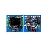
STEVAL-IHP001V3
Description
BOARD SMART PLUG STM32 SPZB260PR
Manufacturer
STMicroelectronics
Series
Zigbee™ SmartPlugr
Type
Microcontroller, Energy Meteringr
Specifications of STEVAL-IHP001V3
Frequency
2.4GHz
For Use With/related Products
STM32F10x, SPZB260-PRO, STPM01
Lead Free Status / RoHS Status
Lead free / RoHS Compliant
Other names
497-10677


STPM01
8.21
SPI interface
The SPI interface supports a simple serial protocol, which is implemented in order to enable
a communication between some master system (microcontroller or PC) and the device.
Three tasks can be performed with this interface:
- remote resetting the device,
- reading data records,
- writing the Mode bits and the configuration bits (temporarily or permanently);
Four pins of the device are dedicated to this purpose: SCS, SYN, SCLNCN, SDATD. SCS,
SYN and SCLNLC are all input pins while SDATD can be input or output according if the SPI
is in write or read mode. A high level signal for these pins means a voltage level higher than
0.75 x V
The internal register are not directly accessible, rather a 32 bit of transmission latches are
used to pre-load the data before being read or written to the internal registers.
The condition in which SCS, SYN and SCLNLC inputs are set to high level determines the
idle state of the SPI interface and no data transfer occurs.
Any pin above has internal weak pull up device of nominal 15 µA. This means that when
some pin is not forced by external signals, the state of pin is logic high. A high state of any
input pin above is considered as an idle (not active) state. For the SPI to operate correctly
the STPM01 must be correctly supplied as described in the power supply section. Idle state
of SPI module is recognized when the signals of pins SYN, SCS, SCLNLC and SDATD are
in a logic high state. Any SPI operations should start from such idle state. The exception to
this rule is when STPM01 has been put into mode of standalone application. In such mode it
can happen that states of pins SCLNLC, SDATD and SYN are not high due to states of
corresponding internal status bits.
When SCS is active (low), signal SDATD should change its state at trailing edge of signal
SCLNLC and the signal SDATD should be stable at next leading edge of signal SCLNLC.
The first valid bit of SDATD is always started with activation of signal SCLNLC.
– BANK: it is used to activate RC oscillator (see
– SCS: as already described in the document, when STPM01 is in standalone mode,
– SYN: this pin operates different functions according to the status of SCS pin. When
– SCLNLC: it is basically the clock pin of the SPI interface. This pin function is also
– SDATD is the Data pin. If SCS is low, the operation of SDATD is dependent on the
the SYN, SCLNLC and SDATD are used also for providing information on the meter
status (see
using the above pins for SPI communication even when the STPM01 is working in
standalone mode, in fact SCS pin enables SPI operation when low. In this section, the
SYN, SCLNLC and SDATD operation as part of the SPI interface is described.
SCS is low the SYN pin status select if the SPI is in read (SYN=1) or write mode
(SYN=0). When SCS is high and SYN is also high the results of the input or output
data are transferred to the transmission latches.
controlled by the SCS status. If SCS is low, SCLNCL is the input of serial bit
synchronization clock signal. When SCS is high, SCLNLC is also high determining
the idle state of the SPI.
status of SYN pin. if SYN is high SDATD is the output of serial bit data (read mode) if
SYN is low SDATD is the input of serial bit data signal (write mode). If SCS is high
SDATD is input of idle signal.
CC
, while a low level signal means a voltage value lower than 0.25 x V
Table
5) and are not used for SPI communication. The SCS pin allows
Doc ID 10853 Rev 7
Chapter
8.12.1).
Theory of operation
CC
.
39/60
Related parts for STEVAL-IHP001V3
Image
Part Number
Description
Manufacturer
Datasheet
Request
R

Part Number:
Description:
BOARD EVAL FOR MEMS SENSORS
Manufacturer:
STMicroelectronics
Datasheet:

Part Number:
Description:
KIT DEV STARTER ST10F276Z5
Manufacturer:
STMicroelectronics
Datasheet:

Part Number:
Description:
BOARD EVAL HDMI $ VIDEO SWITCH
Manufacturer:
STMicroelectronics
Datasheet:

Part Number:
Description:
BOARD DEMO ACCELEROMETER DIL24
Manufacturer:
STMicroelectronics
Datasheet:

Part Number:
Description:
BOARD STLM75/STDS75/ST72F651
Manufacturer:
STMicroelectronics
Datasheet:

Part Number:
Description:
EVAL BOARD 3AXIS MEMS ACCELLRMTR
Manufacturer:
STMicroelectronics
Datasheet:

Part Number:
Description:
BOARD EVAL 8BIT MICRO + TDE1708
Manufacturer:
STMicroelectronics
Datasheet:

Part Number:
Description:
EVAL BOARD A/D TS4657
Manufacturer:
STMicroelectronics
Datasheet:

Part Number:
Description:
BOARD ADAPTER 20DIP LIS3LV02DL
Manufacturer:
STMicroelectronics
Datasheet:

Part Number:
Description:
BOARD DEMO STM8S207R6/LIS331DLH
Manufacturer:
STMicroelectronics
Datasheet:

Part Number:
Description:
STMicroelectronics [RIPPLE-CARRY BINARY COUNTER/DIVIDERS]
Manufacturer:
STMicroelectronics
Datasheet:
Part Number:
Description:
STMicroelectronics [LIQUID-CRYSTAL DISPLAY DRIVERS]
Manufacturer:
STMicroelectronics
Datasheet:
Part Number:
Description:
BOARD EVAL FOR MEMS SENSORS
Manufacturer:
STMicroelectronics
Datasheet: