STEVAL-IHP001V3 STMicroelectronics, STEVAL-IHP001V3 Datasheet - Page 51
STEVAL-IHP001V3
Manufacturer Part Number
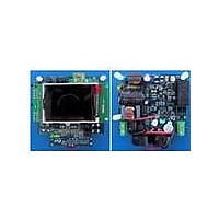
STEVAL-IHP001V3
Description
BOARD SMART PLUG STM32 SPZB260PR
Manufacturer
STMicroelectronics
Series
Zigbee™ SmartPlugr
Type
Microcontroller, Energy Meteringr
Specifications of STEVAL-IHP001V3
Frequency
2.4GHz
For Use With/related Products
STM32F10x, SPZB260-PRO, STPM01
Lead Free Status / RoHS Status
Lead free / RoHS Compliant
Other names
497-10677


STPM01
STPM01 calibration
As shown in
Table
18, only analog parameter are object of calibration because introduce a
certain error. Voltage ADC amplification Av is constant, while Ai is chosen according to used
sensors.
The calibration algorithm will firstly calculate the voltage divider ratio and, as final result, the
correction parameters, called Kv and Ki, which applied to STPM01 voltage and current
measures compensate small tolerances of analog components that affect energy
calculation.
Since Kv and Ki calibration parameters are the decimal representation of the corresponding
configuration bytes CHV and CHP or CHS (respectively voltage channel, primary current
channel and secondary current channel calibration bytes), at the end of calibration CHV and
CHP or CHS (according to the current channel under calibration, primary or secondary
respectively) bits' values are obtained.
In the following procedure CHV, CHP and CHS will be indicated as Cv and Ci.
Through hardwired formulas Kv and Ki tune measured values varying from 0,75 to 1 in 256
steps, according to the value of Cv and Ci (from 0 to 255).
To obtain the greatest correction dynamic initially calibrators are set in the middle of the
range, thus obtaining a calibration range of 12.5 % per voltage or current channel:
Calibrator’s value
Kv = Ki = 0.875
Ci = Cv = 128
In this way it is possible to tune Kv and Ki having a precise measured: for example Cv = 0
generates a correction factor of -12.5 % (Kv = 0.75) and Cv = 255 determines a correction
factor of +12.5 % (Kv = 1), and so on.
According to what pointed out above, the following formulas, which relate Kv, i and Cv, i are
obtained:
Kv,i = (Cv,i/128) * 0.125 + 0.75
Cv,i = 1024 * Kv,i - 768.
The calibration procedure will output Cv and Ci values that will allow the above power
sensitivity of the meter.
This sensitivity is used to calculate target frequency at LED pin for nominal voltage and
current values:
X
= f * 64;
F
with:
f = PM * In * Vn / 3600000;
From values above and for both chosen amplification factor A
=32 and initial calibration data,
I
the following target values can be calculated:
Target RMS reading for given In:
X
= In * K
* A
* Ki * G
* G
* G
* B
/ (V
* 1000) = 1573
I
S
I
INT
DF
DIF
I
BG
Target RMS reading for given Vn:
X
= f * B
* B
* D
/ (f
* X
) = 852
V
V
I
UD
M
I
The output of the voltage divider is then:
Doc ID 10853 Rev 7
51/60
Related parts for STEVAL-IHP001V3
Image
Part Number
Description
Manufacturer
Datasheet
Request
R

Part Number:
Description:
BOARD EVAL FOR MEMS SENSORS
Manufacturer:
STMicroelectronics
Datasheet:

Part Number:
Description:
KIT DEV STARTER ST10F276Z5
Manufacturer:
STMicroelectronics
Datasheet:

Part Number:
Description:
BOARD EVAL HDMI $ VIDEO SWITCH
Manufacturer:
STMicroelectronics
Datasheet:

Part Number:
Description:
BOARD DEMO ACCELEROMETER DIL24
Manufacturer:
STMicroelectronics
Datasheet:

Part Number:
Description:
BOARD STLM75/STDS75/ST72F651
Manufacturer:
STMicroelectronics
Datasheet:

Part Number:
Description:
EVAL BOARD 3AXIS MEMS ACCELLRMTR
Manufacturer:
STMicroelectronics
Datasheet:

Part Number:
Description:
BOARD EVAL 8BIT MICRO + TDE1708
Manufacturer:
STMicroelectronics
Datasheet:

Part Number:
Description:
EVAL BOARD A/D TS4657
Manufacturer:
STMicroelectronics
Datasheet:

Part Number:
Description:
BOARD ADAPTER 20DIP LIS3LV02DL
Manufacturer:
STMicroelectronics
Datasheet:

Part Number:
Description:
BOARD DEMO STM8S207R6/LIS331DLH
Manufacturer:
STMicroelectronics
Datasheet:

Part Number:
Description:
STMicroelectronics [RIPPLE-CARRY BINARY COUNTER/DIVIDERS]
Manufacturer:
STMicroelectronics
Datasheet:
Part Number:
Description:
STMicroelectronics [LIQUID-CRYSTAL DISPLAY DRIVERS]
Manufacturer:
STMicroelectronics
Datasheet:
Part Number:
Description:
BOARD EVAL FOR MEMS SENSORS
Manufacturer:
STMicroelectronics
Datasheet: