XE1205SKC868XE1 Semtech, XE1205SKC868XE1 Datasheet - Page 12
XE1205SKC868XE1
Manufacturer Part Number
XE1205SKC868XE1
Description
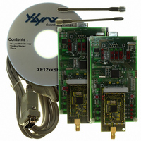
KIT STARTER FOR XE1205 868MHZ
Manufacturer
Semtech
Series
TrueRF™r
Type
Transceiver, ISMr
Specifications of XE1205SKC868XE1
Frequency
868MHz
For Use With/related Products
XE1205 (868MHz)
Lead Free Status / RoHS Status
Contains lead / RoHS non-compliant


The time diagram of an RSSI measurement is given in Figure 5. When the RSSI function has been activated the signal
strength is periodically measured and the result is stored in RSSI_out_int; this result is transferred to the register
RXParam_RSSI_out(1:0) each time this register is read via the SPI interface. TS_RSSI is the wake-up time required
after the function has been activated to get a valid result and its value is given in section 4.2.2. TS_RSSIM is the period
between two successive measurements and its value depends on the selected frequency deviation (100 μs for Δf > 20
kHz, 200 μs for 10 kHz < Δf ≤ 20 kHz, 300 μs for 7 kHz < Δf ≤ 10 kHz, 400 μs for 5 kHz < Δf ≤ 7 kHz, and 500 μs Δf ≤ 5
kHz).
Saout_rssi is internally generated during a read sequence of RXParam_RSSI_out register.
The RSSI block can also be used in interrupt mode by setting the bit IRQParam_RSSI_int to 1. When RSSI_out_int is
equal or greater than a predefined value stored in IRQParam_RSSI_thr(1:0), the signal IRQParam_RSSI_signal_detect
(can be read in the Configuration register) goes high and an interrupt signal RSSI_irq is generated. This interrupt signal
can be used by a microcontroller if IRQParam_RX_irq_0 is set to “01” (see table 5).The interrupt is cleared by writing a 1
to the bit IRQParam_RSSI_signal_detect. If the bit IRQParam_RSSI_int remains high, the process starts again. The next
figure shows the timing diagram of RSSI in interrupt mode.
© Semtech 2008
IRQParam_RSSI_int
RSSI_out_int
IRQParam_RSSI_signal_detect
RSSI_irq
saout_rssi
NSS_CONFIG
RSSI_out_int
RXParam_RSSI_out
RXParam_RSSI
00
00
IRQParam_RSSI_thr = “10”
Figure 6: RSSI generating interrupt signal when detecting a threshold
00
xxx
TS_RSSI
10
xxx
Figure 5: RSSI measurement timing diagram
10
00
val1
00
Read RSSI
00
Clear interrupt
12
TS_RSSIM
00
val2
00
val1
11
val3
10
00
10
val4
Read RSSI
10
XE1205
val4
11
www.semtech.com
00
0
Related parts for XE1205SKC868XE1
Image
Part Number
Description
Manufacturer
Datasheet
Request
R

Part Number:
Description:
Low-power, High Link Budget Integrated Uhf Transceiver
Manufacturer:
Semtech Corporation
Datasheet:

Part Number:
Description:
EVALUATION BOARD
Manufacturer:
Semtech
Datasheet:
Part Number:
Description:
EVALUATION BOARD
Manufacturer:
Semtech
Datasheet:
Part Number:
Description:
VOLTAGE SUPPRESSOR, TRANSIENT SEMTECH
Manufacturer:
Semtech
Datasheet:
Part Number:
Description:
HIGH VOLTAGE CAPACITORS MONOLITHIC CERAMIC TYPE
Manufacturer:
Semtech Corporation
Datasheet:
Part Number:
Description:
EZ1084CM5.0 AMP POSITIVE VOLTAGE REGULATOR
Manufacturer:
Semtech Corporation
Datasheet:
Part Number:
Description:
3.0 AMP LOW DROPOUT POSITIVE VOLTAGE REGULATORS
Manufacturer:
Semtech Corporation
Datasheet:
Part Number:
Description:
Manufacturer:
Semtech Corporation
Datasheet:
Part Number:
Description:
RailClamp Low Capacitance TVS Diode Array
Manufacturer:
Semtech Corporation
Datasheet:
Part Number:
Description:
Manufacturer:
Semtech Corporation
Datasheet:
Part Number:
Description:
Manufacturer:
Semtech Corporation
Datasheet:
Part Number:
Description:
Manufacturer:
Semtech Corporation
Datasheet: