XE1205SKC868XE1 Semtech, XE1205SKC868XE1 Datasheet - Page 8
XE1205SKC868XE1
Manufacturer Part Number
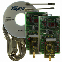
XE1205SKC868XE1
Description
KIT STARTER FOR XE1205 868MHZ
Manufacturer
Semtech
Series
TrueRF™r
Type
Transceiver, ISMr
Specifications of XE1205SKC868XE1
Frequency
868MHz
For Use With/related Products
XE1205 (868MHz)
Lead Free Status / RoHS Status
Contains lead / RoHS non-compliant


The XE1205 is set to receive mode when MCParam_Select_mode is low by setting MCParam_Chip_mode(1:0) to “01”.
If MCParam_Select_mode is high the XE1205 is set to receive mode by setting SW(1:0) to “01”.
5.2.1
The LNA of the receiver has two programmable operation modes: the high sensitivity mode, Mode A, for reception of
weak signals; and the high linearity mode, Mode B, for strong signals. The operation mode is defined by the value of the
Rmode bit in RXParam_Rmode configuration register.
Mode A: High sensitivity mode, RFS approximately 13dB better than in Mode B (see 4.2.2, RFS parameter)
Mode B: High Linearity mode, IIP3 approximately 15dB higher than in Mode A (see 4.2.2, IIP3 parameter)
5.2.2
In receiver mode, two lines are dedicated to interrupt information. The interrupt pins are IRQ_0 and IRQ_1.
IRQ_0 has 3 selectable sources. IRQ_1 has 2 selectable sources. The two following tables summarize the interrupt
management.
5.2.3
In this mode, the receiver has two output signals indicating recovered clock DCLK and recovered NRZ bit DATA. DCLK
is connected to output pin IRQ_1 and DATA is connected to pin DATA configured in output mode. The bit synchronizer
controls the recovered clock signal, DCLK. If the bit synchronizer is enabled by setting the bit /RXParam_Disable_bitsync
to “0” (default value), the clock recovered from the incoming data stream appears at DCLK.
The function of the bit synchronizer is to remove glitches from the data stream and to provide a synchronous
clock at DCLK. The output DATA is valid at the rising edge of DCLK. The following diagram shows the receiver
chain operating in this mode
© Semtech 2008
5.2
IRQParam_RX_irq_0
IRQParam_RX_irq_1
RECEIVER SECTION
LNA & Receiver modes
Interrupt signal mapping
Receiver in continuous mode
00
01
10
11
00
01
10
11
00
01
10
11
00
01
10
11
MCParam_Buffered_mode
MCParam_Buffered_mode IRQ_1
Table 5: IRQ_0 interrupt sources in receive mode.
Table 6: IRQ_1 interrupt sources in receive mode.
0
0
0
0
1
1
1
1
0
0
0
0
1
1
1
1
8
IRQ_0
Output
Output
Output
Output
Output
Output
Output
Output
Output
Output
Output
Output
Output
Output
Output
Output
IRQ_0 Interrupt source
Pattern
RSSI_irq
Pattern
Pattern
No interrupt available
Write_byte
/fifoempty
Pattern
IRQ_1 Interrupt source
DCLK
DCLK
DCLK
DCLK
No interrupt available
Fifofull
RSSI_irq
RSSI_irq
XE1205
www.semtech.com
Related parts for XE1205SKC868XE1
Image
Part Number
Description
Manufacturer
Datasheet
Request
R

Part Number:
Description:
Low-power, High Link Budget Integrated Uhf Transceiver
Manufacturer:
Semtech Corporation
Datasheet:

Part Number:
Description:
EVALUATION BOARD
Manufacturer:
Semtech
Datasheet:
Part Number:
Description:
EVALUATION BOARD
Manufacturer:
Semtech
Datasheet:
Part Number:
Description:
VOLTAGE SUPPRESSOR, TRANSIENT SEMTECH
Manufacturer:
Semtech
Datasheet:
Part Number:
Description:
HIGH VOLTAGE CAPACITORS MONOLITHIC CERAMIC TYPE
Manufacturer:
Semtech Corporation
Datasheet:
Part Number:
Description:
EZ1084CM5.0 AMP POSITIVE VOLTAGE REGULATOR
Manufacturer:
Semtech Corporation
Datasheet:
Part Number:
Description:
3.0 AMP LOW DROPOUT POSITIVE VOLTAGE REGULATORS
Manufacturer:
Semtech Corporation
Datasheet:
Part Number:
Description:
Manufacturer:
Semtech Corporation
Datasheet:
Part Number:
Description:
RailClamp Low Capacitance TVS Diode Array
Manufacturer:
Semtech Corporation
Datasheet:
Part Number:
Description:
Manufacturer:
Semtech Corporation
Datasheet:
Part Number:
Description:
Manufacturer:
Semtech Corporation
Datasheet:
Part Number:
Description:
Manufacturer:
Semtech Corporation
Datasheet: