XE1205SKC868XE1 Semtech, XE1205SKC868XE1 Datasheet - Page 18
XE1205SKC868XE1
Manufacturer Part Number
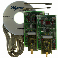
XE1205SKC868XE1
Description
KIT STARTER FOR XE1205 868MHZ
Manufacturer
Semtech
Series
TrueRF™r
Type
Transceiver, ISMr
Specifications of XE1205SKC868XE1
Frequency
868MHz
For Use With/related Products
XE1205 (868MHz)
Lead Free Status / RoHS Status
Contains lead / RoHS non-compliant


The XE1205 is set to transmit mode when MCParam_Select_mode is low by setting MCParam_Chip_mode(1:0) to “10”.
If MCParam
Th
power down to -37dBm at 25kHz for an output power up to 10dBm.
In
In buffered mode the data is first written into the sixteen byte FIFO
m
5.3.1
The output power of the power amplif
to
4.2.2.
5.3.2
The transmitter works in continuous
applied to pin DATA if register bit Data_
the tran smitter chain in continuous mode:
The pulse shaping function is enabled by setting TXParam_Filter to ‘1’. If the filtering option is selected, the DCLK signal
is used as data clock in the transmi
The DCLK signal is supplied to the mi
d
Figure 12 shows an example of filtered data for a bit rate of 4.8kbit/s and a frequency deviation of 5 kHz:
© Semtech 2008
ata is sampled at the rising edge of DCLK and filtered.
odulate the frequency synthesizer.
continuous mode the transmitted data is sent directly to the frequency synthesizer.
e data directly modulates the LO, or
section 7.2.4 below), as shown in Table 10, where RFOP values are given in the Electrical Specifications section
5.3
TRANSMITTE
Output power
Transmitter in continuous mode
_Select_mode is high the XE1205 is set to transmit mode by setting pins SW(1:0) to “10”.
modulator
R SECTION
TXParam_POWER
TXParam_Filter
ssion and this clock is generated at a frequency
Figure 11: Transmitter data path in continuous mode
ier is programmable on four values with the register TXParam_Power (please refer
crocontroller via the pin IRQ_1 which must update th
mode if the bit MCParam_Buffered_
unidir is low or pin NSS_DATA if reg
an (optional) pulse shaping filter can be used resulting in an adjacent channel
0
1
T
able
0 0
0 1
1 0
1 1
10: Output power
Data shaping
Output power
18
filter
settings
RFOP1
RFOP2
RFOP3
RFOP4
via the SPI interface; data from the FIFO is used to
MCParam_Data_unidir
datain
ister bit Data_unidir is high. Figure 11 shows
mode is low. The transmit data should be
according to the selected bit rate.
0
1
e data on the falling edge. The
NSS_DATA
IRQ_1
DATA
XE1205
www.semtech.com
Related parts for XE1205SKC868XE1
Image
Part Number
Description
Manufacturer
Datasheet
Request
R

Part Number:
Description:
Low-power, High Link Budget Integrated Uhf Transceiver
Manufacturer:
Semtech Corporation
Datasheet:

Part Number:
Description:
EVALUATION BOARD
Manufacturer:
Semtech
Datasheet:
Part Number:
Description:
EVALUATION BOARD
Manufacturer:
Semtech
Datasheet:
Part Number:
Description:
VOLTAGE SUPPRESSOR, TRANSIENT SEMTECH
Manufacturer:
Semtech
Datasheet:
Part Number:
Description:
HIGH VOLTAGE CAPACITORS MONOLITHIC CERAMIC TYPE
Manufacturer:
Semtech Corporation
Datasheet:
Part Number:
Description:
EZ1084CM5.0 AMP POSITIVE VOLTAGE REGULATOR
Manufacturer:
Semtech Corporation
Datasheet:
Part Number:
Description:
3.0 AMP LOW DROPOUT POSITIVE VOLTAGE REGULATORS
Manufacturer:
Semtech Corporation
Datasheet:
Part Number:
Description:
Manufacturer:
Semtech Corporation
Datasheet:
Part Number:
Description:
RailClamp Low Capacitance TVS Diode Array
Manufacturer:
Semtech Corporation
Datasheet:
Part Number:
Description:
Manufacturer:
Semtech Corporation
Datasheet:
Part Number:
Description:
Manufacturer:
Semtech Corporation
Datasheet:
Part Number:
Description:
Manufacturer:
Semtech Corporation
Datasheet: