XE1205SKC868XE1 Semtech, XE1205SKC868XE1 Datasheet - Page 24
XE1205SKC868XE1
Manufacturer Part Number
XE1205SKC868XE1
Description
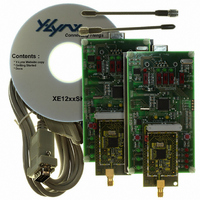
KIT STARTER FOR XE1205 868MHZ
Manufacturer
Semtech
Series
TrueRF™r
Type
Transceiver, ISMr
Specifications of XE1205SKC868XE1
Frequency
868MHz
For Use With/related Products
XE1205 (868MHz)
Lead Free Status / RoHS Status
Contains lead / RoHS non-compliant


7
The XE1205 contains two SPI-compatible serial interfaces, one to send and read the chip configuration, the other to
send and receive data in buffered mode. Both interfaces are configured in slave mode and share the same pins MISO
(Master In Slave Out), MOSI (Master Out Slave In), SCK (Serial Clock). Two additional pins are required to select the
SPI interface: NSS_CONFIG to change or read the transceiver configuration, and NSS_DATA to send or read data.
Figure 14 shows the connections between the transceiver and a microcontroller when buffered mode is used. IRQ_0 and
IRQ_1 are not mentioned in the drawing but can be used.
It is possible to change between the four modes (sleep, stand-by, receive, transmit) by using the two-bit signal SW(1:0).
This option is enabled by setting the bit MCParam_Select_mode to ‘1’ in the configuration register.
A byte transmission can be seen as a rotate operation between the value stored in an 8 bit shift register of the master
device (the microcontroller for instance) and the value stored in an 8 bit shift register of the selected slave device (the
transceiver). The SCK line is used to synchronize both SPI interfaces. Data is transferred full-duplex from master to
slave through the MOSI line and from slave to master through the MISO line. The most significant bit is always sent first.
In both SPI interfaces the rising SCK edge is used to sample the received bit, and the falling SCK edge shifts the data
inside the shift register. Max SCK frequency is 2MHz.
The NSS_CONFIG or NSS_DATA signal is controlled by the master device and should remain low during the byte
transmission. It is not necessary to toggle the NSS_CONFIG signal back to high and back to low between each
transmitted byte. However It is necessary to toggle the NSS_DATA signal back to high and back to low between each
transmitted byte. The transmission is synchronized by the NSS_CONFIG or NSS_DATA signal. While the NSS_CONFIG
or NSS_DATA is high, the counters controlling transmission are reset. Reception starts with the first clock cycle after the
falling edge of NSS_CONFIG or NSS_DATA; if either signal goes high during a byte transmission the counters are reset
and the byte has to be retransmitted.
© Semtech 2008
7.1
SERIAL INTERFACE DEFINITION AND PRINCIPLE OF OPERATION
SERIAL CONTROL INTERFACE
XE1205
CORE
Figure 14: Connection between SPI DATA, SPI CONFIG and a micro-controller
XE1205
(slave)
CONFIG
DATA
(slave)
SPI
SPI
NSS_CONFIG
MOSI
MISO
SCK
NSS_DATA
24
MOSI
MISO
SCK
NSS_DATA
NSS_CONFIG
(master)
µC
XE1205
www.semtech.com
Related parts for XE1205SKC868XE1
Image
Part Number
Description
Manufacturer
Datasheet
Request
R

Part Number:
Description:
Low-power, High Link Budget Integrated Uhf Transceiver
Manufacturer:
Semtech Corporation
Datasheet:

Part Number:
Description:
EVALUATION BOARD
Manufacturer:
Semtech
Datasheet:
Part Number:
Description:
EVALUATION BOARD
Manufacturer:
Semtech
Datasheet:
Part Number:
Description:
VOLTAGE SUPPRESSOR, TRANSIENT SEMTECH
Manufacturer:
Semtech
Datasheet:
Part Number:
Description:
HIGH VOLTAGE CAPACITORS MONOLITHIC CERAMIC TYPE
Manufacturer:
Semtech Corporation
Datasheet:
Part Number:
Description:
EZ1084CM5.0 AMP POSITIVE VOLTAGE REGULATOR
Manufacturer:
Semtech Corporation
Datasheet:
Part Number:
Description:
3.0 AMP LOW DROPOUT POSITIVE VOLTAGE REGULATORS
Manufacturer:
Semtech Corporation
Datasheet:
Part Number:
Description:
Manufacturer:
Semtech Corporation
Datasheet:
Part Number:
Description:
RailClamp Low Capacitance TVS Diode Array
Manufacturer:
Semtech Corporation
Datasheet:
Part Number:
Description:
Manufacturer:
Semtech Corporation
Datasheet:
Part Number:
Description:
Manufacturer:
Semtech Corporation
Datasheet:
Part Number:
Description:
Manufacturer:
Semtech Corporation
Datasheet: