DM303006 Microchip Technology, DM303006 Datasheet - Page 13
DM303006
Manufacturer Part Number
DM303006
Description
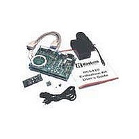
KIT EVALUATION KEELOQ
Manufacturer
Microchip Technology
Series
KEELOQ®r
Type
KeeLoq®r
Specifications of DM303006
Silicon Manufacturer
Microchip
Kit Contents
Main Board, 2 Transmitters, Cables And Power Supply
Tool / Board Applications
General Purpose MCU, MPU, DSP, DSC
For Use With
KeeLoq
Lead Free Status / RoHS Status
Request inventory verification / Request inventory verification
For Use With/related Products
Keeloq Encoders & Decoders
Lead Free Status / RoHS Status
Lead free / RoHS Compliant, Request inventory verification / Request inventory verification


3.0.6
Opening a selected Encoder or Trans-coder model
allows the user to view and edit its functional parame-
ters.
FIGURE 3-12: AN EXAMPLE ENCODER CONFIGURATION DIALOG BOX
While the number and type of configurable parameters
vary from model to model, all dialog boxes share a sim-
ilar template.
The Decoder field Links the Encoder to a particular
decoder; the decoder which the encoder must be com-
patible with.
The Serial Number field displays the most recently
assigned encoder serial number in the current project.
There are several Format configuration options;
Baud Rate (speed) selection field, Modulation format
(PWM, Manchester) and Low Voltage Trip Point Select.
The number of options varies with the selected
Encoder model.
Several Check Boxes to enable and disable various
feature like a Start Pulse or a Minimum number of Code
Words per transmission
The standard Status line to communicate success
and/or Failure of a Programming attempt.
2001 Microchip Technology Inc.
Note:
Control Buttons
Linked Decoder
Format config.
Serial Number
Check boxes
Status line
At least one decoder must be defined
in the project before an encoder can be
programmed.
ENCODER CONFIGURATION AND
PROGRAMMING
K
EE
L
OQ
®
EVALUATION KIT II USER’S GUIDE
Several Control Buttons:
• “Program Mode” freezes the current configura-
• “Default Values” restores a predetermined safe
• “Advanced Mode” enables additional input/
• “Close” will register any configuration changes
• “Help” gives access to a help page relative to the
As previously mentioned, Encoder DIP samples may
be programmed either by placing them in the appropri-
ate Programming Socket or by “In-Circuit Programing”,
if mounted on a demo transmitter connected to the
Transmitter Programming Connector.
tion. The button then changes to a “Program”
button for subsequent programming attempts.
configuration (including grayed out advanced
options).
configuration fields that are otherwise disabled
and grayed-out. The button is present only in
complex encoder models and gives the user
access to the most complete set of configuration
options available for the part.
and close the dialog box.
selected part.
DS41155A-page 11
Related parts for DM303006
Image
Part Number
Description
Manufacturer
Datasheet
Request
R

Part Number:
Description:
Manufacturer:
Microchip Technology Inc.
Datasheet:
Part Number:
Description:
Manufacturer:
Microchip Technology Inc.
Datasheet:
Part Number:
Description:
Manufacturer:
Microchip Technology Inc.
Datasheet:
Part Number:
Description:
Manufacturer:
Microchip Technology Inc.
Datasheet:
Part Number:
Description:
Manufacturer:
Microchip Technology Inc.
Datasheet:
Part Number:
Description:
Manufacturer:
Microchip Technology Inc.
Datasheet:
Part Number:
Description:
Manufacturer:
Microchip Technology Inc.
Datasheet:
Part Number:
Description:
Manufacturer:
Microchip Technology Inc.
Datasheet: